I used the sound sensor I’ve done a few days ago and a little paper-boat + a servo and a box and this is the result :)
This how the puppet works:
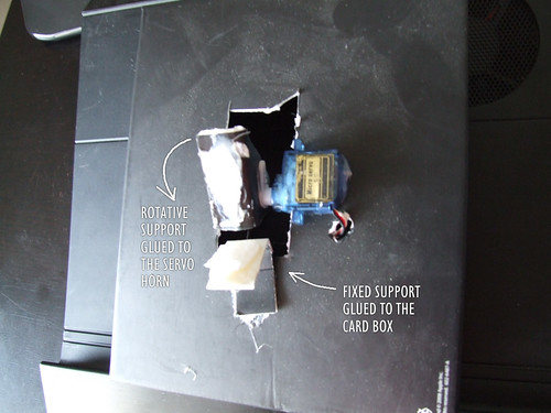
A hole was digger on a card box, and the micro servo is glued to the box as you can see.
One piece of paper is glued to the servo horn, and this will make the puppet talk movement.
Another piece of paper is glued to the box and it will be fixed and hold the puppet.
This is how the puppet is glued to the paper supports. ;)
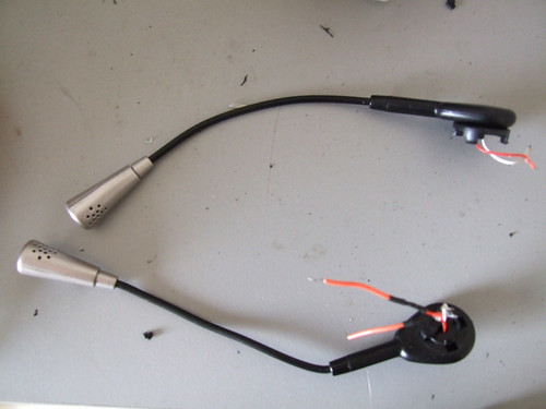
First here are the photos deleted by mistake from flickr:
Headsets microphones
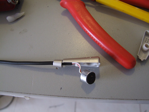
Electrec thingey inside.
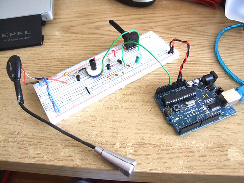
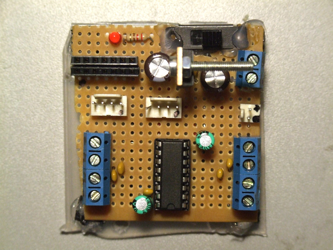
The circuit
This is a closeup of the circuit, I´ve added a 10uF capacitor to stabilize the output signal (it´s the green cap on the right).
The problem here is that I can´t imagine myself soldering all this components onto a pcb, I would like to have at least two of these, four would be awesome.
Click the following button to see source code for Arduino and Processing
27-August-2009 UPDATE:
My friend Gerhard from Germany asked me to build a walkthrough regarding the G-Remote, with part list, schematics and code. And here it is. Enjoy :D
This is my first attempt to make a custom remote controller, and also my first customized Arduino.
After seeing this post made by OddBot I wanted to try to make one myself.
I figured out that if I purchased one remote controller it would be cheaper than buying two of these and paying shipment to Portugal.
So, ripping the guts from a game remote controller I get two joysticks, a couple of buttons, two nice motors and one small lcd.
Each joystick have one button inside, that is cool :-)
Now I have more control over my bots, specially the ones with two motors.. will post videos later.
This came up with the need of having the arduino permanently installed on the robots, I´m tired of having to remove the arduino from one bot to the other, and then rewire everything, and then reupload the code everytime I have a new idea, or everytime I want to show the bot to someone.
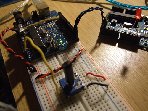
So I followed the ITP Physical Computing tutorial, and it works like a charm, now I want to try to upload code with the FTDI cable, and If I have success on this I can start making my custom Arduino boards. :D
And here´s the trick to upload code without having to remove the chip to a normal Arduino board, and then put it back on the breadboard, I´m using an FTDI cable, Black and Red connect to GND and +V, he RX from the FTDI cable goes to the AVR’s TX (pin3) and the FTDI’s TX goes to AVR’s RX (pin2).
“I hold down the reset button, press the upload button, count to three, then release the reset button. Then the IDE seems to upload the smoothest.” Full credits to Rudolph for sharing the trick.
Another mighty trick is using a 0.01 uf cap between the RTS (green wire) and reset pin, it will make an auto reset before uploading!!! I´ve made my day!! :D Thank you Rory ;)
After long research and trial and error, I´ve came up to a new walkthrough regarding this nice chip, the L293D.
Each project is one project and each one has its own unique power configurations, so you must be aware of the best battery choice and how to distribute voltage through your robot.
I strongly advice you to read the following articles:
L293D gives you the possibility to control two motors in both directions – datasheet
************************************************
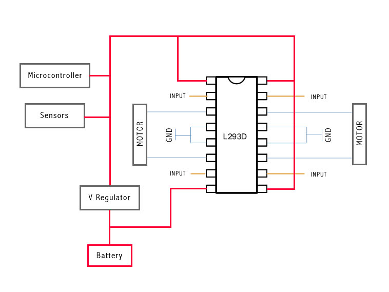
The L293D Circuit:
Basic Implementation:
This is the most basic implementation of the chip.
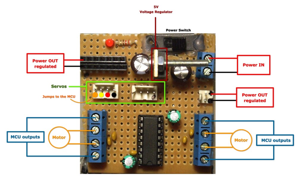
As you can see, a 5V Voltage Regulator is between the battery and pins 1, 9, 16.
Pin 8 gets power before the VReg, if your motor needs for example 6V you should put 6V directly in this pin, all the other pins should not get more than 5V.
This will work with no problem at all, but if you want to do the right implementation take a look at the next example:
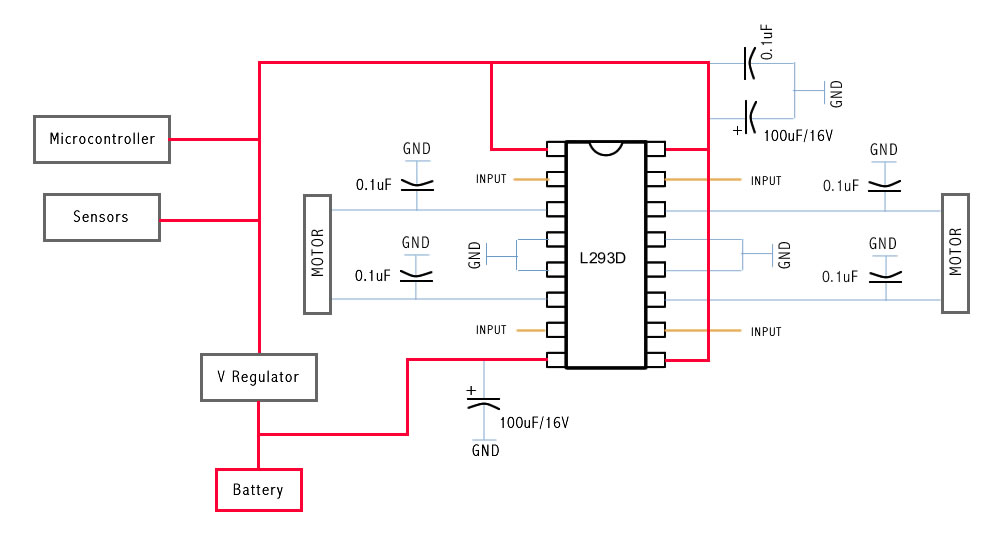
This is the correct Implementation (with the capacitors), and note that pin 8 is feeded by unregulated voltage. This means that if your motors need more than 5V, you should power this pin with that amount of voltage, and the rest of the circuit with 5V.
The capacitors stabilize the current.
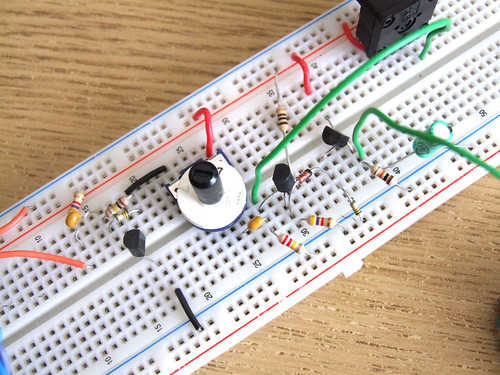
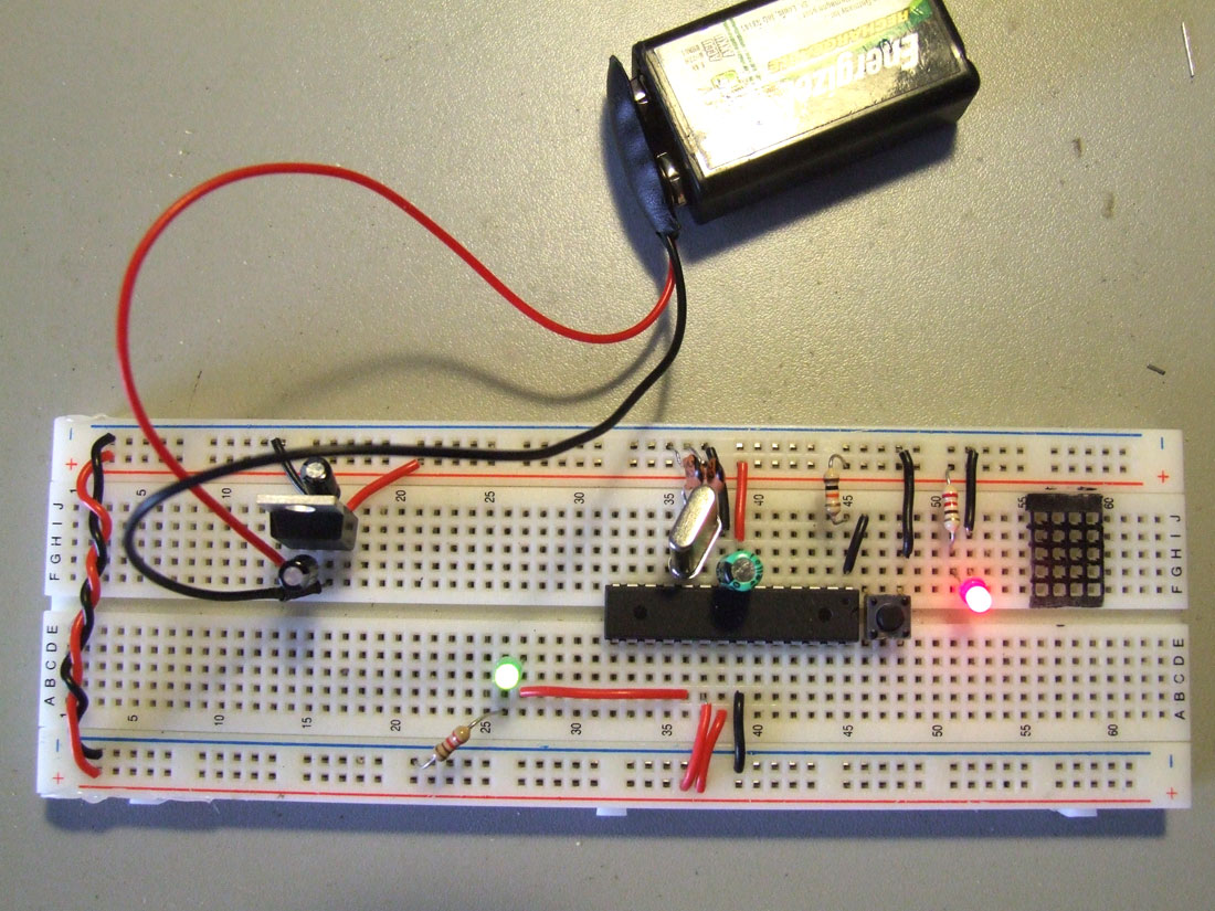
The same circuit on a breadboard:
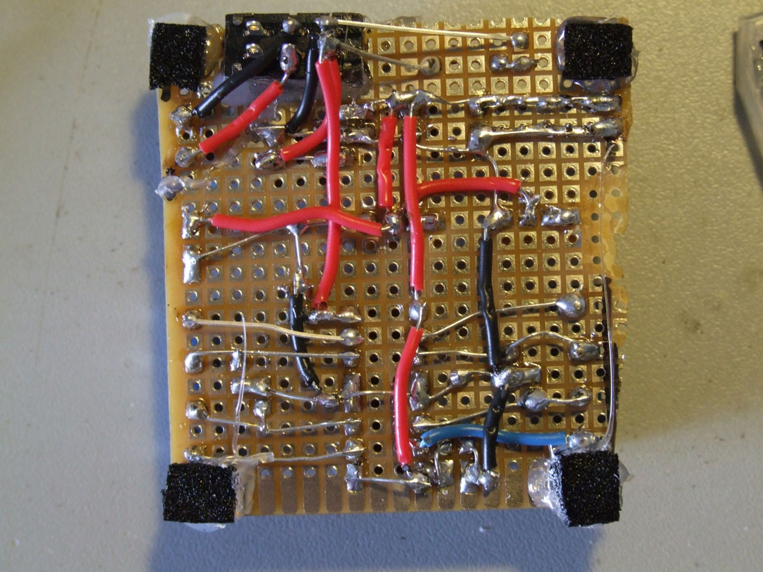
Soldered on a pcb and ready to go:
This is the back of the circuit, click for high resolution photo.
// Use this code to test your motor with the Arduino board:// if you need PWM, just use the PWM outputs on the Arduino// and instead of digitalWrite, you should use the analogWrite command// ————————————————————————— Motorsint motor_left[] = {2, 3};
int motor_right[] = {7, 8};
// ————————————————————————— Setupvoidsetup() {
Serial.begin(9600);
// Setup motorsint i;
for(i = 0; i < 2; i++){
pinMode(motor_left[i], OUTPUT);
pinMode(motor_right[i], OUTPUT);
}
}
// ————————————————————————— Loopvoidloop() {
drive_forward();
delay(1000);
motor_stop();
Serial.println(”1");
drive_backward();
delay(1000);
motor_stop();
Serial.println(”2");
turn_left();
delay(1000);
motor_stop();
Serial.println(”3");
turn_right();
delay(1000);
motor_stop();
Serial.println(”4");
motor_stop();
delay(1000);
motor_stop();
Serial.println(”5?);
}
// ————————————————————————— Drivevoid motor_stop(){
digitalWrite(motor_left[0], LOW);
digitalWrite(motor_left[1], LOW);
digitalWrite(motor_right[0], LOW);
digitalWrite(motor_right[1], LOW);
delay(25);
}
void drive_forward(){
digitalWrite(motor_left[0], HIGH);
digitalWrite(motor_left[1], LOW);
digitalWrite(motor_right[0], HIGH);
digitalWrite(motor_right[1], LOW);
}
void drive_backward(){
digitalWrite(motor_left[0], LOW);
digitalWrite(motor_left[1], HIGH);
digitalWrite(motor_right[0], LOW);
digitalWrite(motor_right[1], HIGH);
}
void turn_left(){
digitalWrite(motor_left[0], LOW);
digitalWrite(motor_left[1], HIGH);
digitalWrite(motor_right[0], HIGH);
digitalWrite(motor_right[1], LOW);
}
void turn_right(){
digitalWrite(motor_left[0], HIGH);
digitalWrite(motor_left[1], LOW);
digitalWrite(motor_right[0], LOW);
digitalWrite(motor_right[1], HIGH);
}
Esta tradução foi feita com o consentimento do seu autor.
O artigo original encontra-se aqui.
Todas e quaisquer questões relativamente ao seu conteúdo deverão ser discutidas no forum LMR (se possivel em inglês) .
Todas e quaisquer questões relativas à tradução para português por favor comuniquem ao tradutor (eu) .
——————————————————————————-
Este projecto não requere conhecimento de electrónica, e não está no âmbito deste projecto aprofundar muito neste sentido, apenas vai fazer com que dês o primeiro passo na construção de um robot muito rapidamente. É baseado num sistema chamado Picaxe que apesar de ser muito simples é também bastante poderoso. Se quizeres experimentar outra plataforma igualmente simples e robusta existe o Arduino. Tens aqui um projecto simples que usa um Arduino e uma breadboard para construir um simples perseguidor de luz.
I´ve created this example to make two Arduinos talk in a simple and clear fashion.
You will see below an example with wires, and another one without wires.
Aqui vai a tradução à muito esperada deste tutorial, espero que vos seja útil.
Decidi remover a Ponte-H, o motor agora está directamente ligado às pilhas AA e o Arduino é alimentado por uma pilha de 9V. Este pequeno robot apenas anda em frente (para já).
Na 2ª parte vou adiccionar a Ponte-H e dois botões Bump. Assim o nosso pequeno robot poderá evitar obstáculos mudando de direcção.