UPDATE: I decided to remove the H-Bridge part, now the motors are directly connected to the AA batteries, and the Arduino is connected to the 9V battery. This little bot will move only forward.
In Part II, I will add an H-Bridge and two SPDT Bump Switches. The robot will move in both directions and avoid obstacles.
————————————————————
Hi! And Welcome to the Easy Arduino Robot Tutorial – Part I !!
For your own sake read this before you move further : ]
Index:
1 – Introduction
2 – Before Start
3 – Parts List
4 – Hello Hardware!
5 – Assemble Process
5.1 – First Car
5.2 – Second Car
5.3 – Servo and front wheels
5.4 – Batteries
5.5 – The Circuit
5.6 – The Servo
5.7 – LDR
6 – Program!!!
—————————————————
1 – Introduction
In this tutorial you will see that you don´t have to be an electronic guru, or a super skilled programmer to make a simple, easy and funny robot.
It won´t have any IR sensor or ultrasonic.
So what will this robot do.. you may ask..
It will be an insane light seeker!!
If you decide to follow this tutorial, at least you should be able to use a breadboard, and if possible to do a little solder, and a bit of hot glue.
————————————————–
2 – Before Start
————-
Have you ever used one BREADBOARD ?
Here you have a nice tutorial and explanation on the way it works:
http://letsmakerobots.com/node/596
————-
In section 4 I will show you how to read analog inputs and how to make one servo move but..
If you don´t know:
– how to blink a LED;
– read a potenciomenter analog input;
– use the Serial command;
– understand the basics of OOP (Object Oriented Program).
I suggest you to visit this link:
Here is a nice set of tutorials:
http://itp.nyu.edu/physcomp/Tutorials/Tutorials
http://todbot.com/blog/bionicarduino/
http://todbot.com/blog/spookyarduino/
NOTE:
Always take one step at a time. Every time you assemble something test it, and if you are successful, move on to the next step.
This is a good practice, and it will make you save precious time and patience.
—————————————————
3 – Parts list:
Generic parts:
1 Arduino Diemicila
1 Breadboard
1 Servo
2 LDR (Light Dependant Resistance)
2 10k resistors
2 On / off switchs
5 – 1 Ohm resistor (this will depend on your motor power)
Prototype Wires (colored if possible)
Customizable parts:
Batteries – it depends on your motors needs
I will use:
1 9V battery with power plug to connect to the Arduino
3 AA NiMh to power the motor
————
I choose to use toys instead of premade parts. It is faster to get them and they are also cheap, and fun to work with. Besides, it enhances your criativity and you get used to be a solution finder.
————
In 1 Euro stores, or chinese stores you can find lots of cheap toys, waiting to be vandalized! : )
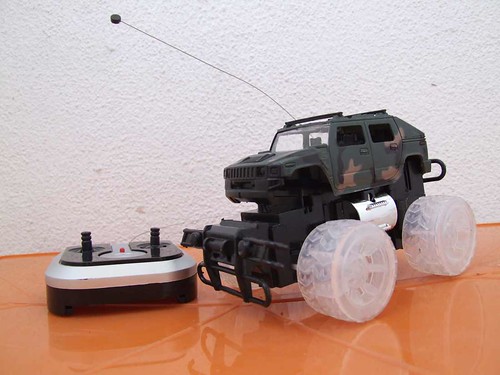
This one was 5€ and I will use its chassis as a platform

This little car was 2€ and I will use its front wheels for steering.
——————————————————–
4 – Hello Hardware:
LDR – Light Dependant Resistors
This part is for beginners in Arduino, I will show briefly how to move a servo, and read analog inputs through LDR´s.
———–
Reading LDR analog inputs:
The LDR can be placed in either way and so do the resistors. This means they don´t have a + or – .

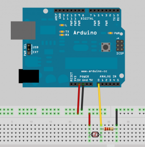
Take one wire and connect into one Arduino Analog Pin of your choice
———–
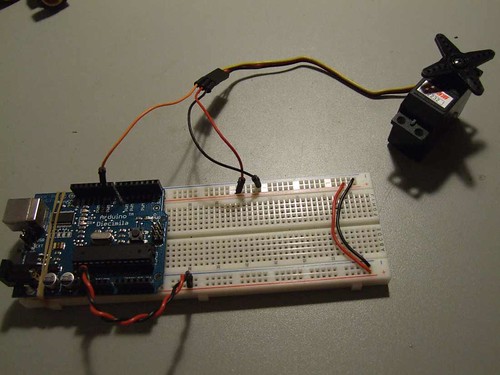
Now for the Servo:
Before you use the servo code, you must install Servotimer1 library. Unpack it into your hardware/libraries folder to add the library. Then restart the Arduino Software.
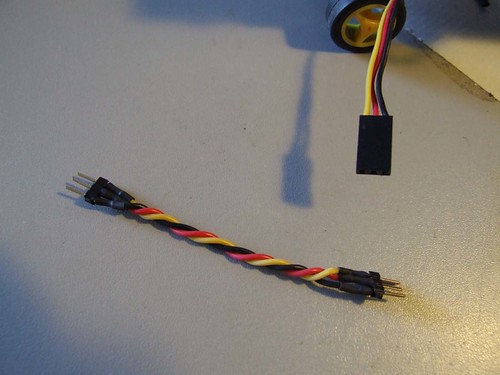
Take the black wire that comes from the servo and plug it into the black line on the breadboard, the Red wire into the red line on the breadboard, and the Yellow wire into the Arduino pin 9.
Take two more wires and connect the 5V on the Arduino into the red line on the breadboard and the GND on the Arduino into the black line on the breadboard.
The Arduino can be powered from USB cable.
Now that you are more familiar with Arduino bits and bytes, LET THE FUN BEGIN :D
———————————————————
5 – Assemble Process
5.1 – First Car
Disassemble the car which will provide platform for components and also traction system, and remove all the parts except the rear wheels and the motor.
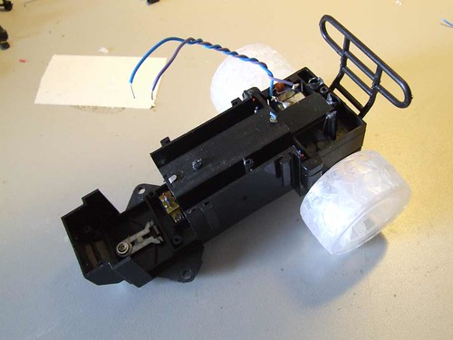
Solder two cables to the motor pins.
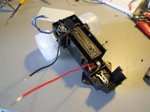
Also soldered one black wire to the Ground pin on the battery case and one red wire to the power switch.
This was the first and the last time you see soldering in this tutorial. :)
———–
5.2 – Second Car
Another little car was vandalized, this time I will use the front wheels to have the steerings.
———–
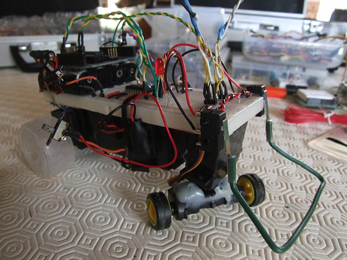
5.3 – Servo and Front Wheels:

This is not a very pretty glue work i know.. try to center the wheels the best you can.
Next, I used hot glue to place the servo next to the chassis.
ATTENTION: Certify that both wheels touch the ground when turning, otherwise you might have problems.
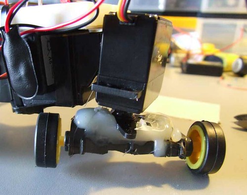
Left wheel doens´t touch the ground = PROBLEM

Both wheels touch the ground = Problem solved : ]
———–
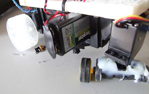
5.4 – Batteries
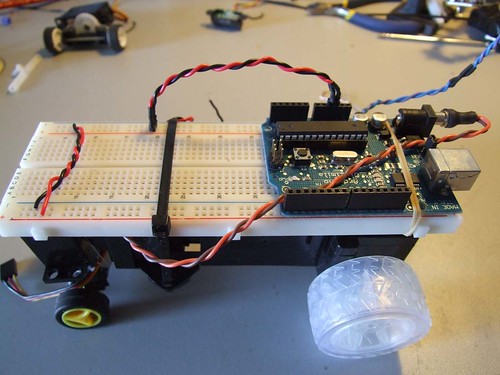
I was lucky with this little car. The 9V battery fits perfectly inside the chassis, and I can use the 3 AA batteries case, and save space to put the breadboard on the top.

———–
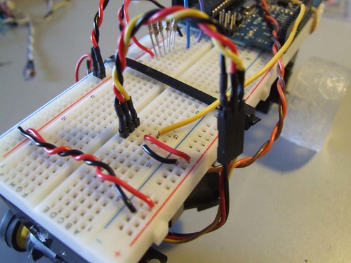
5.5 – The Circuit
The Arduino is plugged from the 9V battery.
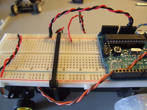
Red and black wires connect the 5V and Ground from the Arduino to the breadboard main row´s.
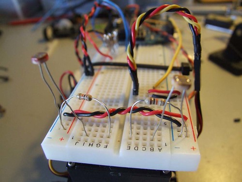
Now connect the Red wire from the AA batts into one row of the breadboard
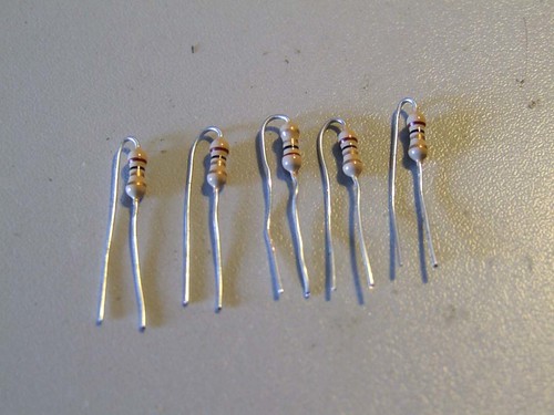
Next, I will use five resistor´s of 1 ohm between the motor and the 3 AA batts.
This is low value resistors, each one of this resistors will make the motor go slower.
I could use only one resistor of 5 ohms, but using five of 1 ohm, I can have better control on the motor power.
If I want less or more motor power, I will remove or add another 1 ohm resistor.
This way the motor won´t burn out and it still has got a good speed.

Note the Ground wire is connected to another row.
And this way I connect the motor wires. Turn on the power and see if it moves forward and if has enough power to drive your robot.
———–
5.6 – The Servo
Connect the Servo to the breadboard.
Grab two wires and connect them into the breadboard main row´s 5V and Ground.
Grab another wire and connect the Servo Signal wire into Digital Pin 9 on the Arduino.
———–
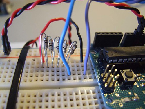
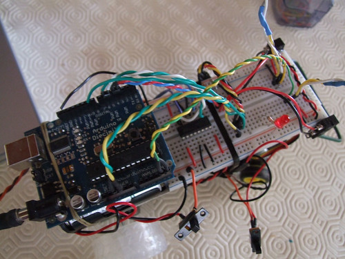
5.7 – LDR
Final step:
Place the LDR and resistors, they don´t have + or -. So you can place them in any direction.
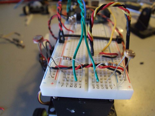
The green wires to connect them into the Arduino Analog Input Pins 4 and 5.
——————
( test the LDR as you did before)
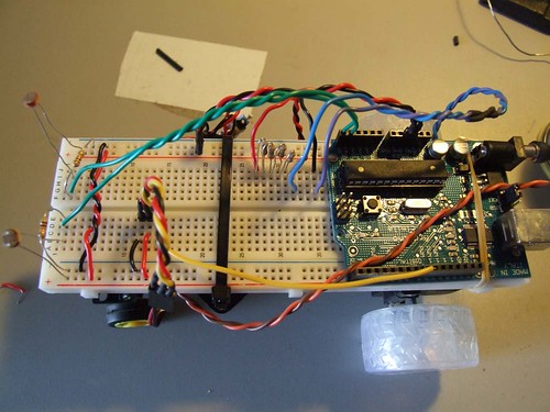
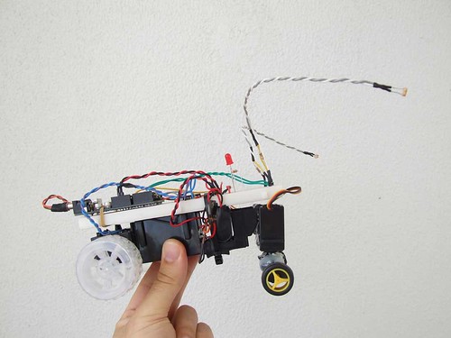
This is the final look of our circuit.
Every physical steps are done! So now let´s upload some code into the Arduino.
———————————————————
6 – Program!!!
——————————————————-
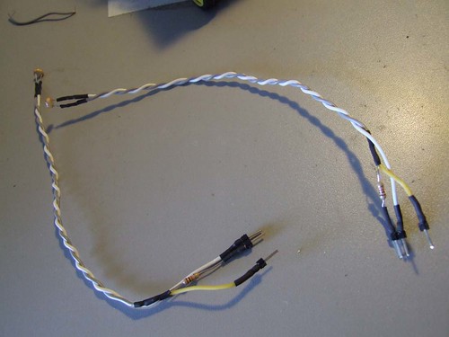
I´ve made the LDR antennas longer so it can be more sensitive to light variations.
——————————————————-

———————————————————
I hope you find this tutorial useful!! And I hope to see your Arduino robots posted soon ;)
———————————————————
———————————————————
———————————————————
5 . Feb . 2009
just to say there won´t be any part I, I apologize for this.
I´ve done it, but its a bit wacky, too many wires and connections just to achieve a stupid goal… it was a good intention though..
sorry mates
i tried this out with the delemonove but it never work… when the one ldr is exposed to light it turns the servo and when it is not it turns the other way but the other ldr doesnt so anything at all