This came up with the need of having the arduino permanently installed on the robots, I´m tired of having to remove the arduino from one bot to the other, and then rewire everything, and then reupload the code everytime I have a new idea, or everytime I want to show the bot to someone.
So I followed the ITP Physical Computing tutorial, and it works like a charm, now I want to try to upload code with the FTDI cable, and If I have success on this I can start making my custom Arduino boards. :D
The link below might be of interest:
Burning the bootloader without an external AVR-Writer
=================================================================
Update: 18.03.09
And here´s the trick to upload code without having to remove the chip to a normal Arduino board, and then put it back on the breadboard, I´m using an FTDI cable, Black and Red connect to GND and +V, he RX from the FTDI cable goes to the AVR’s TX (pin3) and the FTDI’s TX goes to AVR’s RX (pin2).
“I hold down the reset button, press the upload button, count to three, then release the reset button. Then the IDE seems to upload the smoothest.” Full credits to Rudolph for sharing the trick.
Another mighty trick is using a 0.01 uf cap between the RTS (green wire) and reset pin, it will make an auto reset before uploading!!! I´ve made my day!! :D Thank you Rory ;)

=================================================================
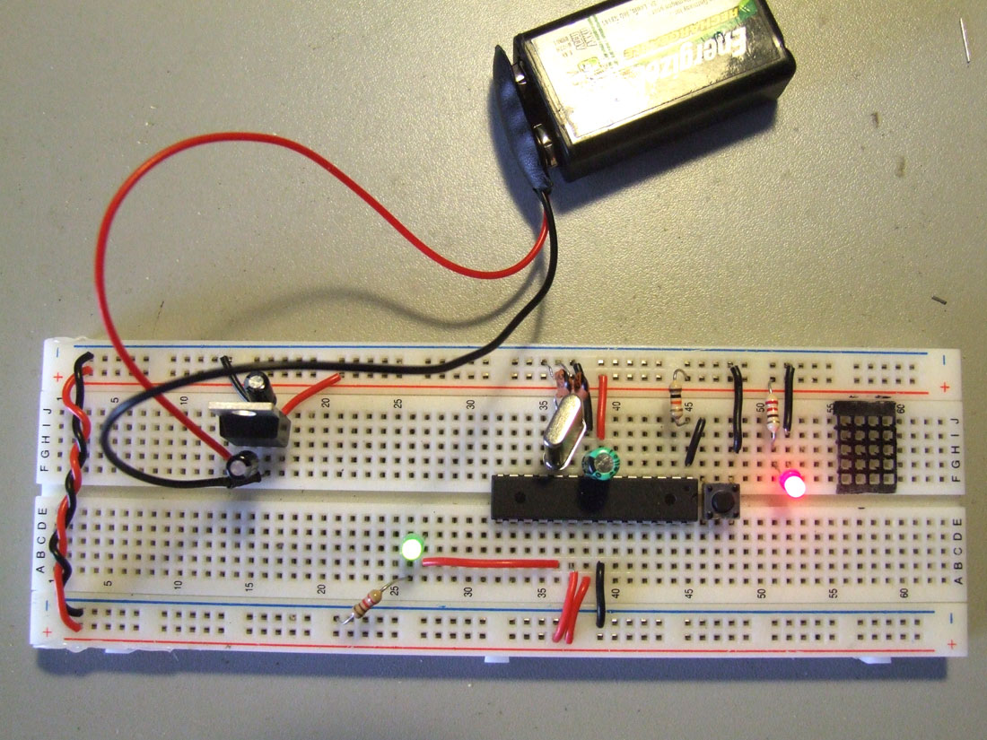
Testing the circuit with the L293D :-)
STOP! The input power is not being filtered through the voltage regulator! Move the – and + from the 9V to J61 and J62 or expect it to suddenly stop working.
This bugs me a lot about the ITP tutorial– they show you how to wire up the voltage regulator, then don’t actually show the thing being powered– grrr!
Thank you for warning me Jeff!
I will correct this ASAP!
Foto Updated ;)
Boas gui,
Conseguiste encontrar samples da ATmega168? ou tiveste de comprar?
Excelente trabalho :)
Cumps
Ainda não encontrei samples, este que estou a usar tirei de outro Arduino só para experimentar :)
I just updated the ITP tutorial with a quick step mentioning where the power supply is to be placed. I hope that it is helpful and I apologize that it wasn’t clear enough.
Any additional feedback would be great!
Olá Guilherme,
Ando há tempos a tentar brincar com motores+Arduino usando este circuito, mas surgiu-me uma dúvida: que uso é que tás a dar aos 5V que saem do regulador?
Neste caso concreto, o motor que quero alimentar é de baixa tensao (daqueles de brinquedos) e portanto 5V chegam. Mas será boa ideia alimentar o motor com a tensão/corrente à saída do regulador?
Neste caso os 5V regulados alimentam todo o circuito.
Convém sempre saber qual a voltagem adequada para o motor que estamos a usar, porque podemos estar a sobrecarregá-lo sem saber, ou no caso inverso podemos não estar a aproveitar toda a sua performance. Se o teu motor operar a uma voltagem de 3V (por exemplo) ao aplicares 5V vais estar a diminuir o seu tempo de vida.
Espero ter ajudado :)