The greatest part of the project is to actually drive the bot and just play with it.. video speaks for itself :]
Tag: Robot

NightRider – update d
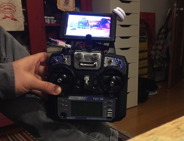
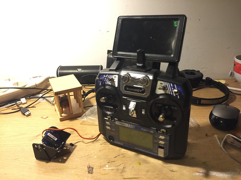
About the controller, I want it to have something we see in the drone industry, a controller with the screen, all-in-one. There is always the option to connect the receiver to the TV, but I really want it to be standalone, independent of power wallets, just something that I can carry anywhere I go.
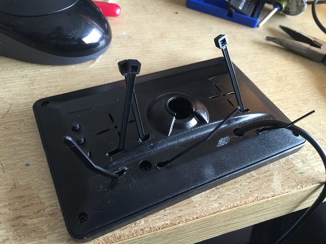
First step was to find a way to hold the screen to the remote, so I added zip ties to the back of the screen.
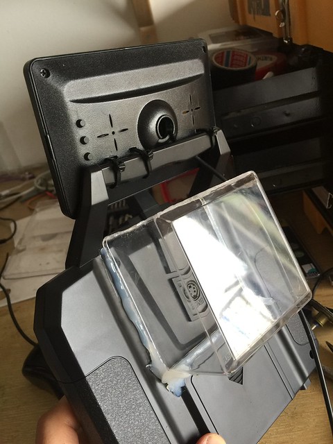
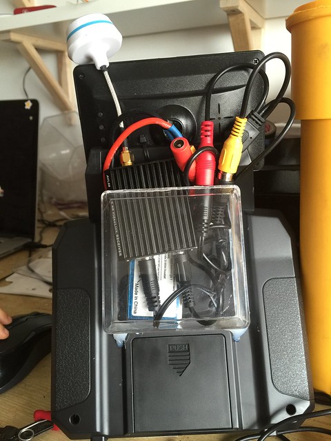
I also added a compartment to hold the receiver, battery and wires (collecting acrylic stuff is a good habit I guess)
Not bad..
The back side is still messy, but I will live with it for now.
and it just works..

NightRider – update b
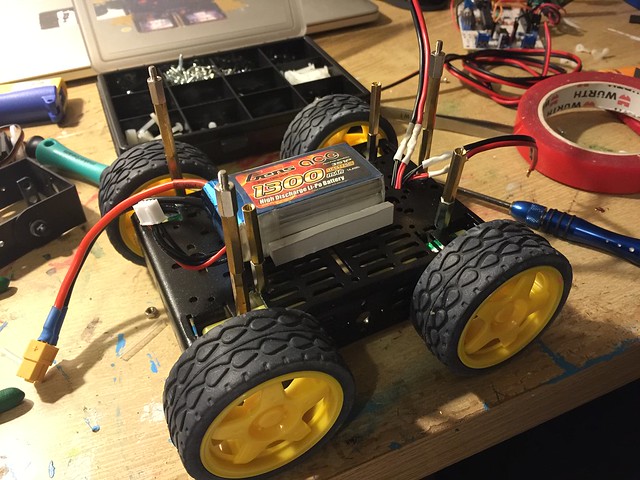
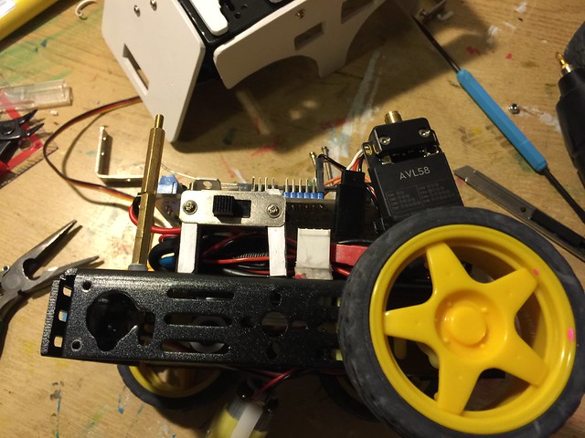
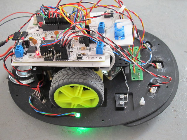
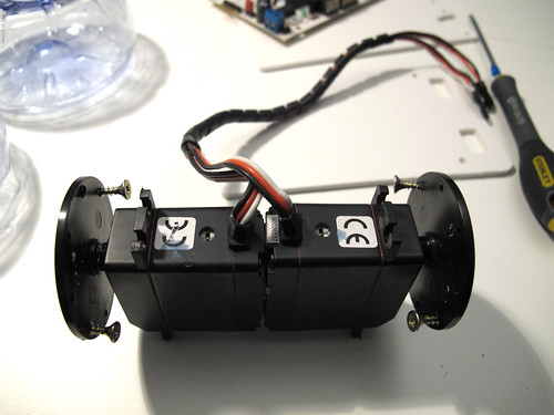
I felt with courage to start the modifications to the bot, first I moved the battery to the lowest possible place, this makes the center of gravity lower.
With the electronics board all looks good..
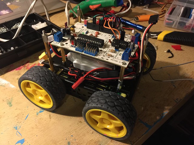
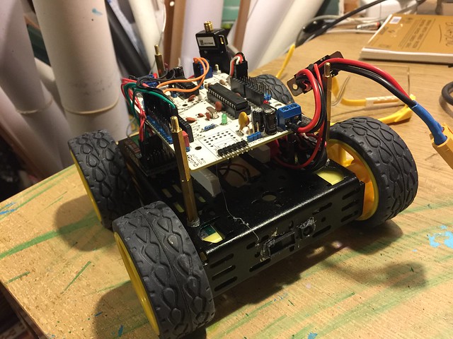
I added a power switch and a Sharp Infra Red sensor, this sensor will act as a fail safe to avoid collisions.
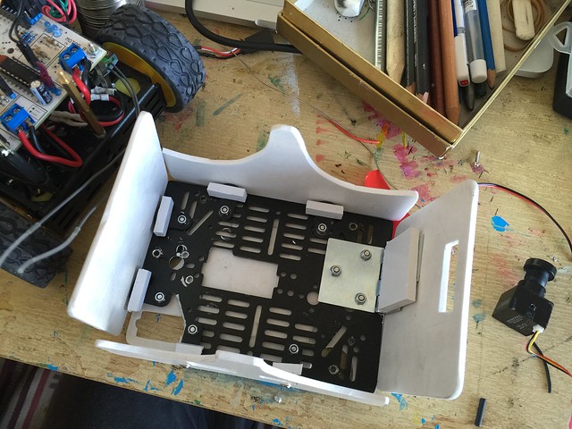
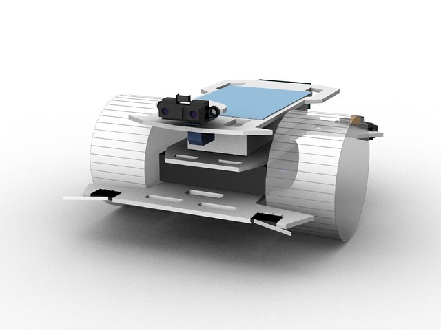
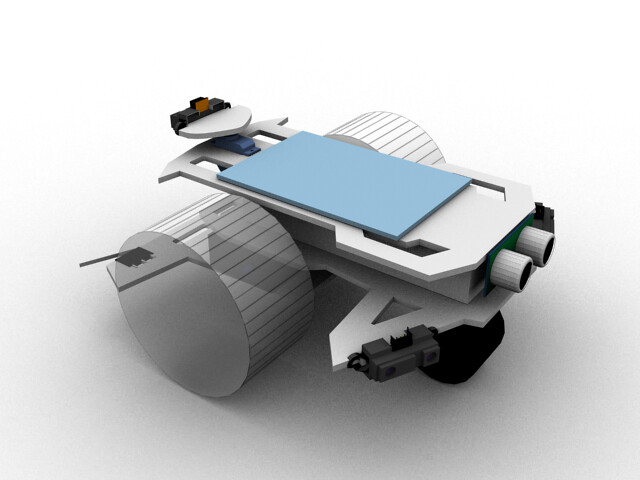
I also wanted to create some kind of a shell, so went to 3D to design the plates and this is the result.
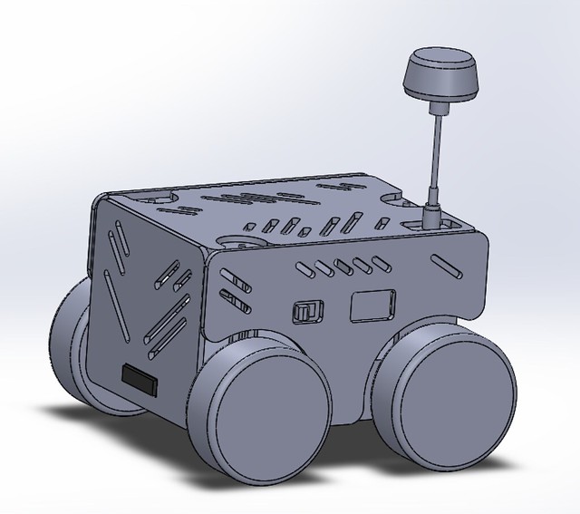
The plates will be cutted in laser or CNC, but meanwhile I will just print them and manually cut PVC sheets.
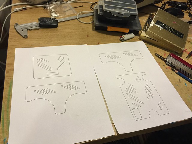
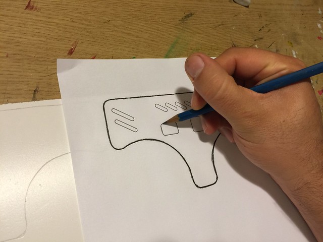
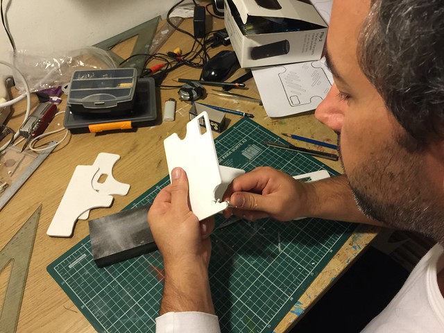
using graphite pencil to transfer the plate drawings to the PVC sheets.
All the plates are transfered and ready to be cutted.

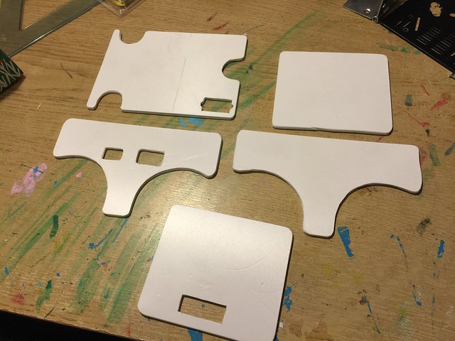
The plates are cutted, now I will just sand a bit to give a final touch
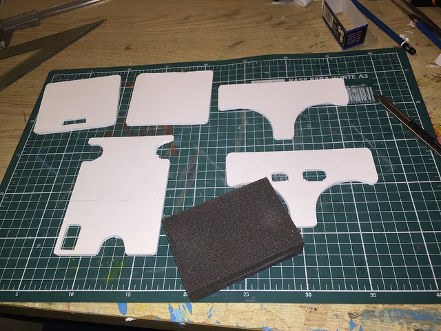
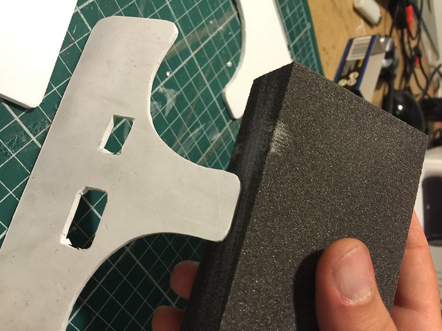
All plates are looking good for now
Time to start with the supports for the plates, I will go to these small L shape things
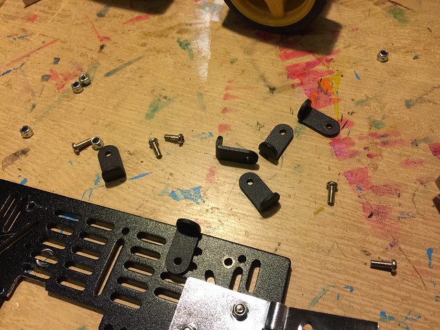
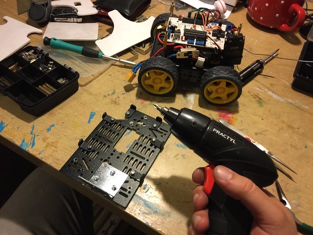
All the supports are fitted, when we have loads of screws an electric screwdriver is handy, this one is the cheapest I could find
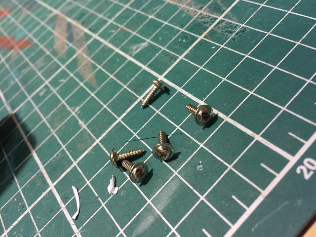
Now to fit the plates I will use this selftap screws, they come together with the servos motors, and I always harvest them because they are hard to find in hardware stores.
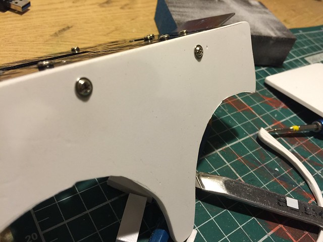
You can also see a hinge, this will actually make a door to swap batteries.
And this is how the plates are securelly fitted.
A look on the inside
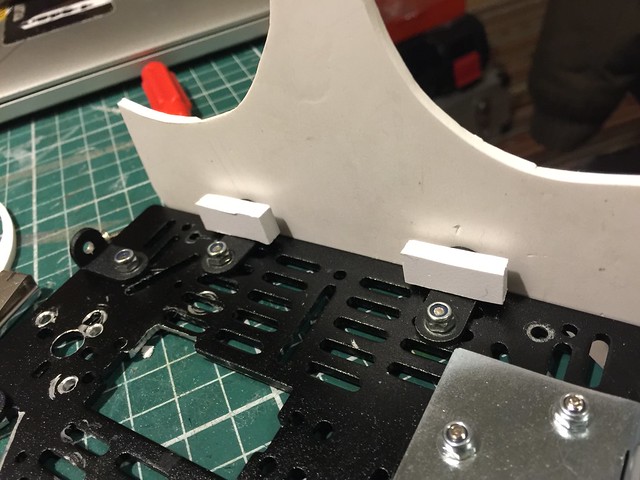
This is how I managed to hold the power button in place, it is just PVC pieces fitted to the chassis, and then hold the power button with selftap screws.
There’s the hinge.
Testing everything, all look good.
I was doing another quick test when suddently smoke started to come out, it was the L293D that got smoked.. well, I couldn’t expect worse since I was pushing 12V to 4 motors and the L293D only handles 600 mAh per channel.
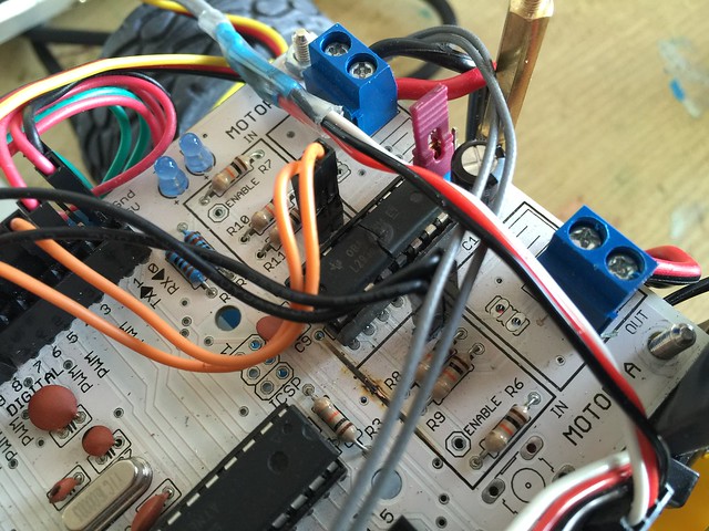
I will swap the board to the new Motoruino2 from Artica, wich is still a prototype but nothing better that this bot to test it.
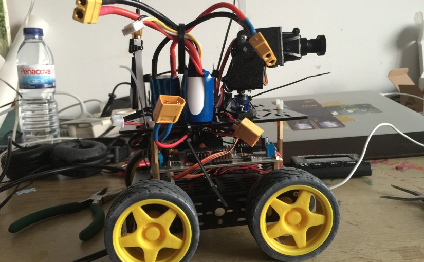
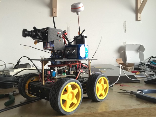
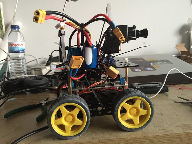
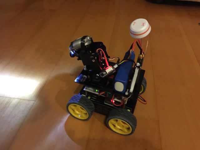
NightRider update A
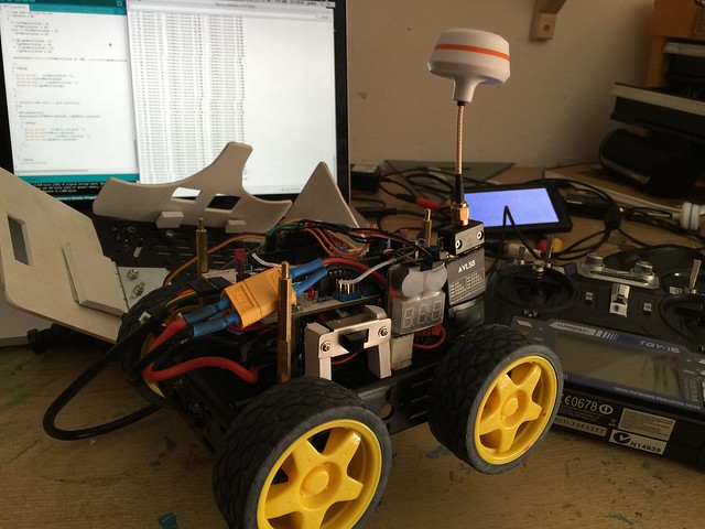
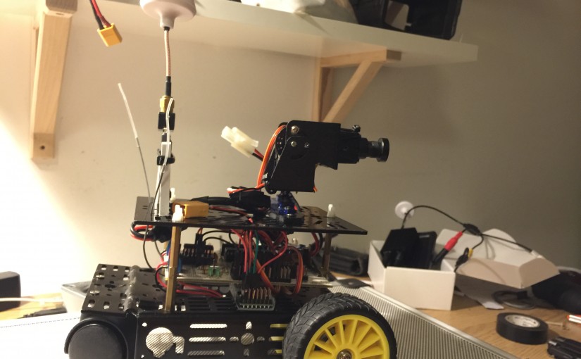
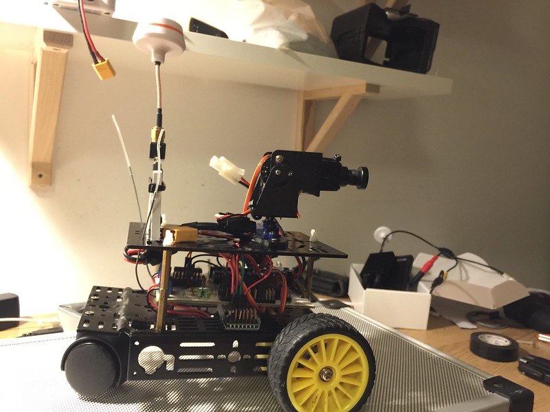
I wasn’t happy with the hacked chassis, besides the caster wheel was freaking out my wife because it was making a lot of noise on the apartment’s pavement. Luckily me I had another brand new chassis, and so decided to swap all the electronics to the new one, and the result is great, glad I did it! With 4WD it moves really quicly and its motion is much more stable, besides I am feeding the motors with a 12V Lipo battery wich gives it a great pump.
The experiences I had are very fun, and the torch light is a great addon.
I still don’t like the way it is, with the battery exposed on the top GC is very high, besides the pan/tilt is very shaky when it moves in full speed.
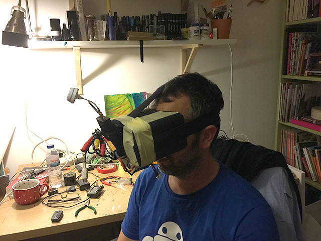
I tried my first FPV experience with the Quanum Goggle Set from HobbyKing and it freak me out, running the thing in full speed and all the shakiness made me almost to throw up (lol). The screen that comes with the kit is just great. I think I will buy another kit just to have another screen.
I stick to the screen and connecting the receiver to the TV wich is great.
For now I will try to stick all the electronics inside the chassis and probably will make a shell for it, or at least try.
NightRider
Back to the Origins
Has been a long time since my last robot project.
Recently everything related to FPV, Drones, and Robots in general have been occupying my mind. I wanted to create an FPV Terrestrial Drone experience to anyone without the need of having (in portugal we say “kit the unhas”, “nails kit”) skills to pilot an aerial drone.
This little project reminds me those times when I have time and patience, to build small robotic creatures just because the fun of it, I guess I’m getting very nostalgic with this one.
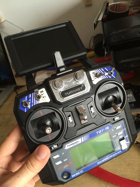
The Turnigy controller works just fine, and to get the sticks values I am using the very well documented code from Sparkfun Nick Poole
https://www.sparkfun.com/tutorials/348
.
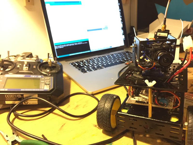
And this is the controller with the screen. There is still missing the video receiver and the battery.
More to come ;]
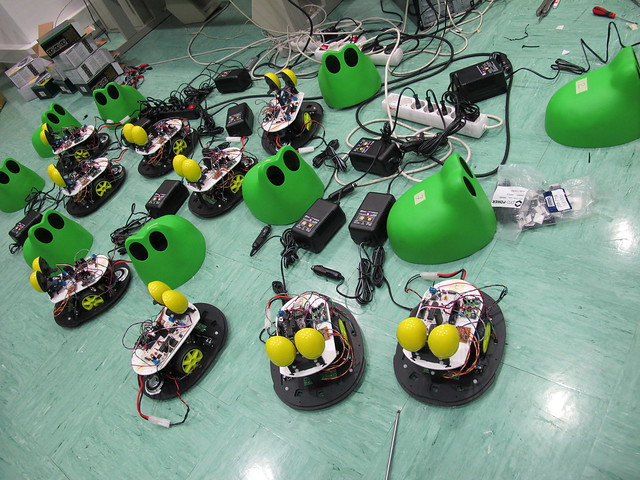
SapoBot
SapoBot is a robot that wonders through spaces avoiding obstacles detects holes on the ground, follow walls and follow lines, to change between behaviors you only need to press the shell, and when he detects a collision gives a frog sound. This project was comissioned by Sapo, means frog in portuguese.
This bots were made with a Farrusco chassis and Motoruino and once again with the great IDMind hardware and electronics skills, all the credits for the eyes mechanics and all the rest of the hardware upgrade goes to them.

The shell was made by Fernando and Margarida Antunes, don’t forget to check their amazing art work at http://margaridantunes.weebly.com.
This is a Farrusco on steroids!! Only the pins 0 and 1 for serial communication are free, all the other pins are taken for a considerable amount of sensors and actuators: 3 infrared sensors to measure distances on the front, 3 infra red sensors facing the ground, a speaker, 1 RGB LED, 1 servo motor, 2 dc motors and 2 bumper micro-switches to detect collisions.
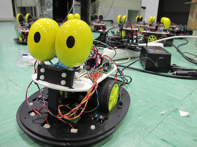
The eyes are meant to give some human expression to the bot, they turn organically to both sides according the direction that the robot takes.
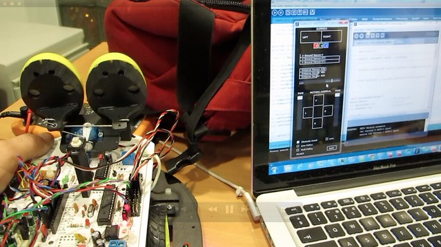
We coded an application in Processing to check all the sensors and actuators, allowing to save settings on the microcontroller EEPROM. This code will be available on Artica’s github soon.
Time to drink some juice :]

And the result is a happy family!
F4WD + ball link
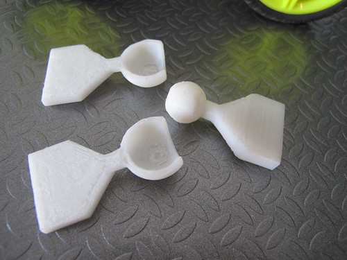
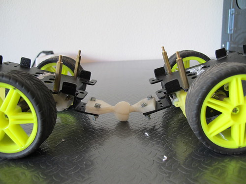
Four wheel drive vehicles have always excited my imagination, and this time I joined two Farrusco’s chassis in front to front as you can see in the picture below:

This way both chassis are fixed on each other (is this correct to say in english??) and I thought it would be cool to have them articulated in some way, so I started to design a ball link and this is the first output (oh, did I mention I have a 3D printer in the office? :D
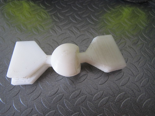
It still need a bit of work because the link needs some kind of lock to prevent the vehicle to bend itself and touch the ground (gosh!! what a crappy english!!)

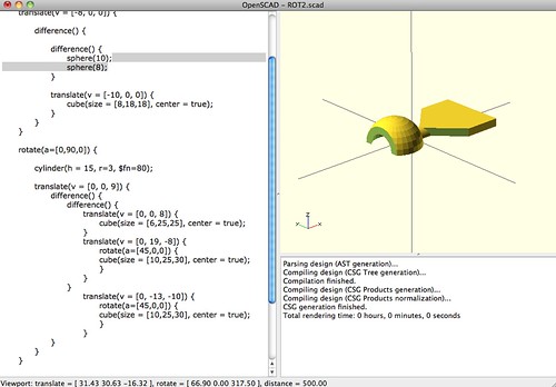
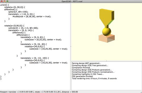
I used OpenSCAD to design the piece, it is a great tool to use because everything is made with simple commands and you can design pretty much everything!! You can download the OpenSCAD files in Thingiverse.
In the next chapter, the redesign!
Complexifying BOTtle
I didn’t feel so happy with this minimalistic chassis design so I felt the need to add some complexity to it. And because I am a 3D lover and because I have some spare time I decided to do what I never use to do: “think before act”. Oh, and the other thing that makes me want to do this is the fact that we have a CNC machine at Artica’s office. So althouth I love to build robots without thinking to much on how is it going to be, when there is a cutting machine evolved there is always the need of planning and design wich is a lot of fun as well!
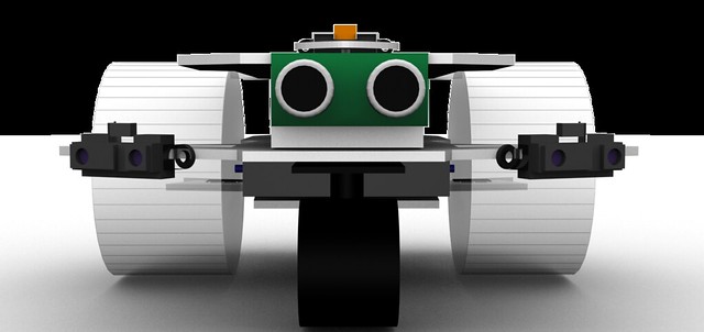
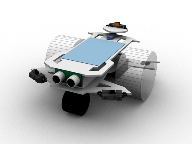
This creature will be able to go in both directions, and for each direction it will have a diferent sensorial setup. On one front there will be an infra-red distance sensor mounted on a servo and two touch sensors to detect colisions. On the other front there will be a sonar distance sensor between two low-range infra-red sensors. This setup will need to use different programming methods for movement and for sensorial perception and will be fun to program.
The design is ready, now let the machine do its job.
BOTtle
BOTtle is a robot like many others but with a particularity, the wheels are made of plastic bottles as you can see in this video:
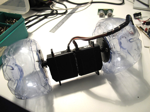
The components I will be using:

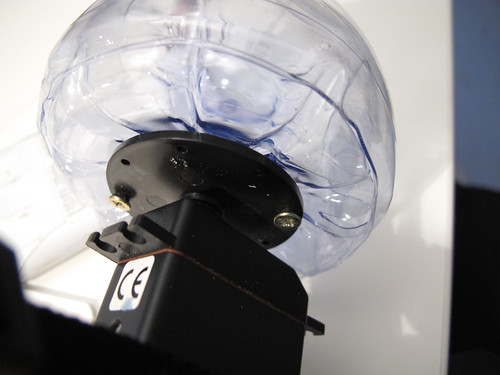
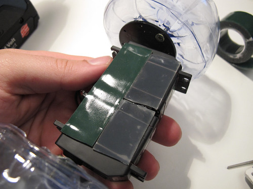
The servos are already attached to one another with double side-tape, I will show you how to attach the wheels to the servo horns

Start by adding wood self-tapping screws to the servo horn just a little in a way they won’t fall
Repeat this process 4 times
Open small holes in the exact place where the screws will be tight. I used a soldering iron.
Tight both screws to the wheels
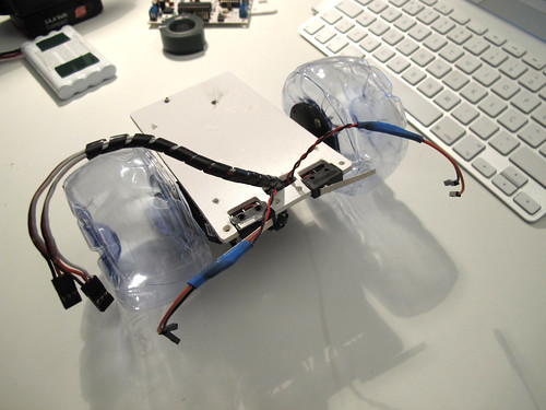
Now I am placing the bumpers on the front of the bot on a PVC sheet (in this post you can see what I have done for a Sharp sensor)

And now the caster wheel, those screws tips are going to be cutted out
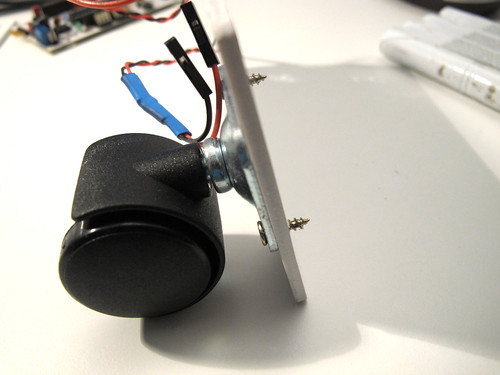
The screw tips are gone and added a bit of super glue because the PVC melted when cutting the screws

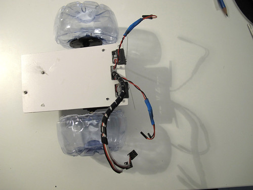
To attach the pvc base to the servos I am using double side rubber tape
And this is what I have done so far, more will be added soon (I hope)
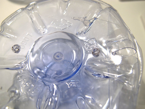
making wheels out of plastic bottles
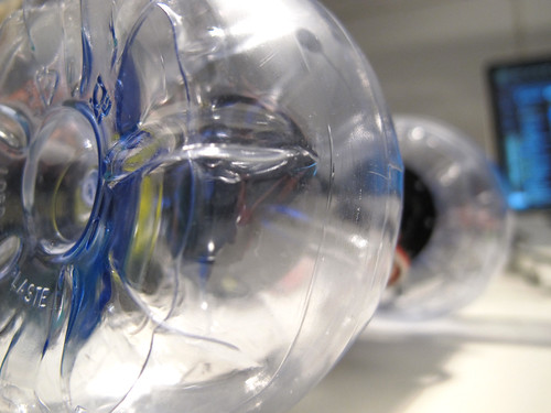
This is an old idea, finally I have the time to show it to the world.
The are bottle shapes that perfectly fit together, you will see how easy it is to create a wheel from two plastic bootles, the video speaks for itself:
Check this post to see how I attached the wheels to a continuos rotation servo.