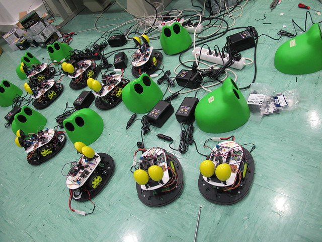
NightRider – update e

The programming.

To capture the RC data I am using a simple Arduino function called pulseIn(). You can see all the reference on the Arduino site. I discovered this function while googling “radio control joystick to arduino” and found this great example from Sparkfun.

All the code is at github.

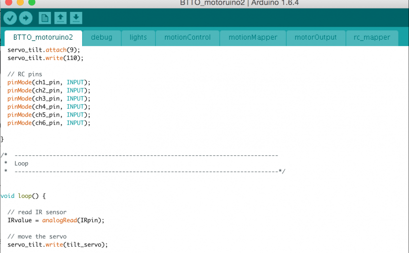
There is a folder called “RC_reader” with a program that captures all the 6 RC channels and prints RAW values to the console. This code it is just for debug purposes and it is not being used for anything else:

int ch1_pin = 6; // right_horizontal
int ch3_pin = 5; // right_vertical

int ch2_pin = 4; // left_vertical
int ch4_pin = 3; // left_horizontal

int ch5_pin = 7; // c_stick
int ch6_pin = 8; // right_knob

int ch1_val; 
int ch2_val;
int ch3_val; 
int ch4_val;
int ch5_val;
int ch6_val;

void setup() {
  Serial.begin(9600); 
  
  // RC pins
  pinMode(ch1_pin, INPUT);
  pinMode(ch2_pin, INPUT);
  pinMode(ch3_pin, INPUT);
  pinMode(ch4_pin, INPUT);
  pinMode(ch5_pin, INPUT);
  pinMode(ch6_pin, INPUT);

}

void loop() {

  ch1_val = pulseIn(ch1_pin, HIGH, 25000); // Read the pulse width of 
  ch2_val = pulseIn(ch2_pin, HIGH, 25000); // each channel
  ch3_val = pulseIn(ch3_pin, HIGH, 25000); // Read the pulse width of 
  ch4_val = pulseIn(ch4_pin, HIGH, 25000);
  ch5_val = pulseIn(ch5_pin, HIGH, 25000); // Read the pulse width of 
  ch6_val = pulseIn(ch6_pin, HIGH, 25000);
  
  Serial.print("ch1: ");
  Serial.print(ch1_val);
  Serial.print("  ch2: ");
  Serial.print(ch2_val);
  Serial.print("  ch3: ");
  Serial.print(ch3_val);
  Serial.print("  ch4: ");
  Serial.print(ch4_val);
  Serial.print("  ch5: ");
  Serial.print(ch5_val);
  Serial.print("  ch6: ");
  Serial.println(ch6_val);
}

Using this code, I am reading raw data from the RC, now we just need to map this data to an usable format (0 – 1023) or (0 – 255) or (0 – 180).

//The actual code have three important functions:

// map RC RAW values to usable values
rc_mapper();

// map usable values to PWM values
motionMapper();

// controls motion with IR sensor and RC control
motionControl();

rc_mapper() – maps the joystick to a differential drive, and once again google made my day, otherwise I would still be struggling with this component. This function will give two values ‘left_vertical’ and ‘right_horizontal’ that will be used later to assign speed to the motors.

motionMapper() – all the source for this function can be seen here. I had to hack this bit of code to use with the Motoruino2, because the motors are on a Slave uC, I am using a function to set PWM for both motors.

motionControl() – just uses the values that comes from the motionMapper() and sends them through the function setPWM(leftMotor, rightMotor).
I am also using the right knob on the remote controller to set maximum velocity.

There is also a Sharp Distance Sensor that is being used to avoid collisions. On the motion control I am testing the distance, and if it is below 100 the bot runs normally, if it is beyond 100 and below 200 it moves slowly, and if it is beyond 200 stops. It can always move backward, there is still some tweak I want to do here, for instance, I want to be able to enable or disable this feature in runtime.

For the light I am using one of the sticks with 3 positions. Each position gives a value, each value will correspond to a light state.

Not to much to say about the servo control. I just need to verify the course limits to avoid collisions with other components on the bot.

All the code is available and commented on GitHub.

Differential wheeled robot simulator

This Processing application is ment to simulate a differential wheeled robot, very used nowadays. This app will be usefull in our Robotics Workshops!

Differential Drive Simulator in Processing

I missed the github class so here it is the good’old zip
Here’s the link to the repo, you’re welcome to contribute ;)

There are still a couple of enhancements on the list:

  • real metrics and scale
  • connect to motor encoders
  • record a path on the virtual world and let the real robot follow it
  • become real simulator of the arduino code used in our robotics workshops

The video is reproduced a lot faster than the program really performs  :p

Some control keys are available:
Differential Drive Simulator in Processing

The overall program is quite simple to use, just pass the mouse over the joystick area to control the bot.
Differential Drive Simulator in Processing

The program basically maps joystick values X and Y to a differential drive system where two motors are used to drive a robot.

There is also a representation of a robot and its path according to the motors differential rotation.

Credits:

The joystick program was based on a program entitled ‘JoystickSimulation’ by: Vince Thompson
http://diyroboticslab.wordpress.com/2009/06/17/joystick-simulation-with-processing/

The robot program was based on a program entitled ‘Kephera Simulator’ by Adam Matic of Croatia
http://gritsgroup.org/robotsimulator.htm

TEDxKids @ CentralTejo

TEDxKids @ CentralTejo

We had the pleasure to be part on the first portuguese TEDxKids!! We brought our Farrusco’s tribe for a brief introduction to robotics during the afternoon, what a great time!! Big thanks to all the TEDxKids team for the opportunity and support!! This kind of events should happen more often!

There will be a TV show dedicated to the event this Saturday and Sunday @ SICNoticias

http://imagensdemarca.sapo.pt/emissoes/tv/pecas/promo-pequenos-grandes-oradores/

Robotic Claw

This is a first experiment on building a 3D printed robotic claw, I first got inspired by this project but it was designed for a micro servo, and I wanted to use a standard size servo so I had to design the claw from scratch.

Robotic Claw

The actual design still need one tweak or two to be optimized for 3D printing, but as it is now is fully functional.

STL files are available at http://www.thingiverse.com/thing:31056

Robotic Claw

SapoBot

SapoBot is a robot that wonders through spaces avoiding obstacles detects holes on the ground, follow walls and follow lines, to change between behaviors you only need to press the shell, and when he detects a collision gives a frog sound. This project was comissioned by Sapo, means frog in portuguese.

This bots were made with a Farrusco chassis and Motoruino and once again with the great IDMind hardware and electronics skills, all the credits for the eyes mechanics and all the rest of the hardware upgrade goes to them.


The shell was made by Fernando and Margarida Antunes, don’t forget to check their amazing art work at http://margaridantunes.weebly.com.


This is a Farrusco on steroids!! Only the pins 0 and 1 for serial communication are free, all the other pins are taken for a considerable amount of sensors and actuators: 3 infrared sensors to measure distances on the front, 3 infra red sensors facing the ground, a speaker, 1 RGB LED, 1 servo motor, 2 dc motors and 2 bumper micro-switches to detect collisions.


The eyes are meant to give some human expression to the bot, they turn organically to both sides according the direction that the robot takes.


We coded an application in Processing to check all the sensors and actuators, allowing to save settings on the microcontroller EEPROM. This code will be available on Artica’s github soon.


Time to drink some juice :]


And the result is a happy family!

Motoruino and Motors – Workshop @ ALTLAB

Last Wednesday Artica lectured a Motoruino workshop at AltLab.
Beside all the participants there were more than a hundred watching a live stream on Ustream, people from Viseu, Guimarães, Porto, Évora, Madrid and many more places I believe.

The central theme was Motoruino and motors such as Servos, DC motors, Steppers and Linear actuators.

In the end we had Farrusco working in Obstacle Avoidance and Following Light mode.


Video streaming by Ustream