Prizes awarded to the top three Arduino projects. Projects will be judged by Shawn Augustson of ArduinoFun.com, Guilherme Martins of Guibot.net, Dr. Alison Colman of theFuseFactory.org, and we will also accept viewer submitted votes through Twitter
How to Enter: Contestants must create a project using the Arduino (any board). The project must be geared towards the beginner to intermediate user to help learn more about what the Arduino is and can do. Project can have already been submitted elsewhere, for example you already published it on another site like Instructables, etc.
Each project MUST HAVE the following in order to be considered:
Photo of the finished project
YouTube or other service video showing the project working
Step by step supporting documentation on how a user can complete your project
Arduino code used for project
List of sources used, for example if you borrowed ideas from another project on the web
(Optional) – Bonus points for adding a statement of what the Arduino has meant to you.
How to Submit Your Project: Send photos, documentation, links to your video and your arduino sketch pasted into a text file to shawn at arduinofun dot com. Projects will then be posted to ArduinoFun.com (you remain the project owner, we will not use projects in anything other than published to ArduinoFun.com)
O Festival de Artes Digitais Olhares de Outono chega este ano à 10ª edição. Os workshops são gratuitos porém, os que têm como objecto a plataforma Arduino implicam a aquisição de kits de material que ficam para o formando. Os interessados podem solicitar mais informações ou realizar uma pré-inscrição através do mail hdias@porto.ucp.pt ou consultar o site: Olhares de Outono, 2009
Os temas dos workshops são:
/// COMUNICAÇÂO SEM FIOS COM O ARDUINO
\\\ TRACKING VIDEO
/// PURE DATA
\\\ ROBÓTICA CRIATIVA
COMUNICAÇÂO SEM FIOS COM O ARDUINO
18 de Nov. (9:30-12:30 e 14:00-17:00) | Duração: 1 dia
Participantes: 10 – 12 | Formador: Filipe Valpereiro
TRACKING VIDEO
19 de Nov. (14:00-18:00) e 20 de Nov. (9:30-12:30 e 14:00-18:00)
Duração: 2 dias | Participantes: 10 – 12 | Formador: Armando Menicacci
PURE DATA, introduction à Pure Data – design sonore.
23 e 24 de Nov. (9:30-12:30 e 14:00-16:00) | Duração: 2 dias
Participantes: 10 – 12 | Formador: Christian Delecluze
ROBÓTICA CRIATIVA
23, 24 e 25 de Nov. (9:30-12:30 e 14:00-17:00) | Duração: 3 dias
Participantes: 10 – 12 | Formador: Guilherme Martins e Filipe Valpereiro
I’ve been working on this for a while and finally I have the courage to post the results.
I’m also testing the pololu micro serial servo controller in the hope I could achieve better results. One good thing the pololu controller has, is the ability to set the speed of the movement, I guess it is a good plus to have this extra control. And using this feature together with the filter you get really cool and smooth movements, check the end of the video.
The point I don’t like in this experience is that the robot shakes a lot, but that is due to the weak support. I will have to arrange a solution to void so much shakiness.
The low pass filter below is what makes the desaceleration while the value reaches the destination point. I’ve posted the full code below the video.
filter: 0.05; // 1 = no filter // has to be between 0.01 and 1
destinationValue = 1000;
destinationValueFiltered = destinationValueFiltered * (1.0-filter) + destinationValue * filter;
Code to move one servo directly connected to the Arduino:
// easing servo movements with low pass filter// the servo signal must be connected directly to the arduino pin 2 // Time interval, this executes one piece of code from time to time// Download Metro lybrary and instructions:// http://www.arduino.cc/playground/Code/Metro
#include <Metro.h>
int duration = 3500; // duration of the interval in milisecondsMetro intervaller = Metro (duration);
// MegaServo library// download and instructions: // http://www.arduino.cc/playground/Code/MegaServo
#include
MegaServo servos;
// servos minimum and maximum position
#define MIN_POS 800 // the minuimum pulse width for your servos
#define MAX_POS 2200 // maximum pulse width for your servos// servo pin
#define s0_pin 2
// variables to hold new destination positionsint d0; // destination0int d0_sh; // destination0 to be smoothed// the filter to be aplied// this value will be multiplied by "d0" and added to "d0_sh"float filtro = 0.05; // 0.01 to 1.0// setup runs once, when the sketch startsvoidsetup() {
// initialize serial comunicationSerial.begin(9600);
// set servo pin
servos.attach(s0_pin);
}
// main program loop, executes forever after setup()voidloop() {
// check the time interval, if it reaches limit "duration" goes back to one // and runs the codeif (intervaller.check() == 1) {
// calculate a new random position between max and min values
d0 = random(MIN_POS, MAX_POS);
// resets interval with a new random duration
intervaller.interval(random(500,2000));
}
// smooth the destination value
d0_sh = d0_sh * (1.0-filtro) + d0 * filtro;
// assign new position to the servo
servos.write(d0_sh);
// delay to make the servo movedelay(25);
}
And this is the code to use with the pololu micro serial servo controller:
// easing servo movements with a low pass filter and Pololu Micro Serial Servo Controller// Time interval, this executes one piece of code from time to time// Download Metro lybrary and instructions:// http://www.arduino.cc/playground/Code/Metro
#include <Metro.h>
int duration = 3500; // duration of the interval in milisecondsMetro intervaller = Metro (duration);
// servos minimum and maximum position
#define MIN_POS 500 // the minuimum pulse width for your servos
#define MAX_POS 5500 // maximum pulse width for your servos// variables to hold new destination positionsint d0; // destination0int d0_sh; // destination0 to be smoothed// the filter to be aplied// this value will be multiplied by "d0" and added to "d0_sh"float filtro = 0.05; // 0.01 to 1.0// set servo speed, goes from 1 to 127int servoSpeed = 120;
// setup runs once, when the sketch startsvoidsetup() {
// initialize serial comunicationSerial.begin(9600);
// set servo pin and speed
servoSetSpeed(0, servoSpeed);
}
// main program loop, executes forever after setup()voidloop() {
// check the time interval, if it reaches limit "duration" goes back to one // and runs the codeif (intervaller.check() == 1) {
// calculate a new random position between max and min values
d0 = random(MIN_POS, MAX_POS);
// resets interval with a new random duration
intervaller.interval(random(500,3000));
}
// smooth the destination value
d0_sh = d0_sh * (1.0-filtro) + d0 * filtro;
// assign new position to the servo
put(0,d0_sh);
// delay to make the servo movedelay(25);
}
// functions from this forum topic:// http://forum.pololu.com/viewtopic.php?f=16&t=745&start=60&st=0&sk=t&sd=avoid put(int servo, int angle)
{
//servo is the servo number (typically 0-7)//angle is the absolute position from 500 to 5500unsignedchar buff[6];
unsignedint temp;
unsignedchar pos_hi,pos_low;
//Convert the angle data into two 7-bit bytes
temp=angle&0x1f80;
pos_hi=temp>>7;
pos_low=angle & 0x7f;
//Construct a Pololu Protocol command sentence
buff[0]=0x80; //start byte
buff[1]=0x01; //device id
buff[2]=0x04; //command number
buff[3]=servo; //servo number
buff[4]=pos_hi; //data1
buff[5]=pos_low; //data2//Send the command to the servo controllerfor(int i=0;i<6;i++){
Serial.print(buff[i],BYTE);
}
}
void servoSetSpeed(int servo, intspeed){
//servo is the servo number (typically 0-7)//speed is servo speed (1=fastest, 127=slowest)//set speed to zero to turn off speed limitingunsignedchar buff[5];
unsignedchar speedcmd;
speedcmd=speed&0x7f;//take only lower 7 bits of speed
buff[0]=0x80;//start byte
buff[1]=0x01;//device id
buff[2]=0x01;//command number
buff[3]=servo;//servo number
buff[4]=speed;//data1for(int i=0;i<5;i++){
Serial.print(buff[i],BYTE);
}
}
This is the final result of the first stage of this project. An installation where zezinho calls for visitors and when a visitor reachs the mixing controllers he waits for new poses.
If you are nearby Lisbon, you can visit zezinho until 9 of July at: FABRICA FEATURES Lisboa. Rua Garrett, nº83 | Megastore United Colors of Benetton, 4º andar | 1200-203 Lisboa
OddBot is going to China, and he created several packs with robotics stuff and came up with a great creative challenge wich is to create a video with the keyword FUN. One of the extra points was to build something with paper, wood, and cheap materials, no techy thing here, the main purpose was to spend a great time creating a cool video to make others laugh. The other extra point was to build a PCB with non PCB materials like, paper, card, or any other thing, I’m so happy to know that paperduino was one of the inspiration to this competition.
“el sapatero” came with this great challenge in mind, and I wanted to build something really nonsense.. and started to play with stuff I have, and my wife appear with this silly boots made out of recycled card. This card boots(?) are used inside shoes to keep their original shape and I knew in that precise moment that I have to use them! :)
and the video for the challenge: http://letsmakerobots.com/node/8630
This was the first layout. I thought that I could build some kind of a walker… but I was wrong :D
This is a motor plug made with polymorph..
Polymorph plugged into the motor and with a plastic bit.. (can’t explain this in english) lol
The polymorph structure was shaped in a way that gives fully support to the card boots.
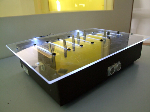
This is the circuit, I wanted to try other non conventional PCB materials, and this time I tried with acrylic. I kinda like it.. its different… but not an easy task.. I don’t know how many hours I spent with this..
It was a great disapointment when I saw that only the body spins.. and the boots remained still.
So I have to create another polymorph structure to give some traction to the entire system.
1st test drive
And the final result :)
I used hotglue to reinforce the card. And this makes a cool accoustic sound coming from the boots :)
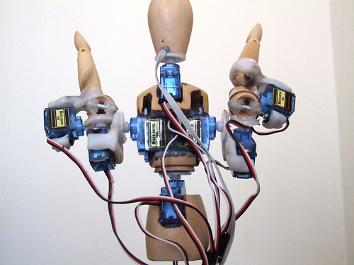
This is Zezinho, a humanoid robot that likes to pose! :)
All the microservo supports where made with the amazing material Polymorph.
For now he is being controlled by 8 analog inputs, each input controls one microservo. In the future (as I hope) he will be controlled by a computer vision system where he will try copy real human poses in real time.
I’m still programming servo control functions and movements presets.
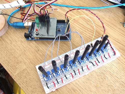
This is the analog inputs setup and a custom servo shield.
I’m using an Arduino Mega because I need more than 6 analog inputs that the regular Arduino boards have and I don’t have the time (or should I say patience) to digg around multiplexers.. I’m very lucky to have the support of InMotion.pt, they sent me the Arduino Mega for the first test drive. Thank you so much Filipe!! ;)
This robot will also be my final project for the course ‘O Som do Pensamento’. It will be an instalation where the user will be able to control his poses with physical controllers. I’ve made a controller box in acrylic and will post photos as soon as I have it with me.
Playing with movements and poses.
Testing movements and different servo speeds.
________________________________________________________________
Update (21.08.09)
Other posts related to Zezinho:
I used the sound sensor I’ve done a few days ago and a little paper-boat + a servo and a box and this is the result :)
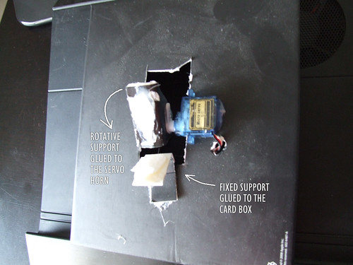
This how the puppet works:
A hole was digger on a card box, and the micro servo is glued to the box as you can see.
One piece of paper is glued to the servo horn, and this will make the puppet talk movement.
Another piece of paper is glued to the box and it will be fixed and hold the puppet.
This is how the puppet is glued to the paper supports. ;)
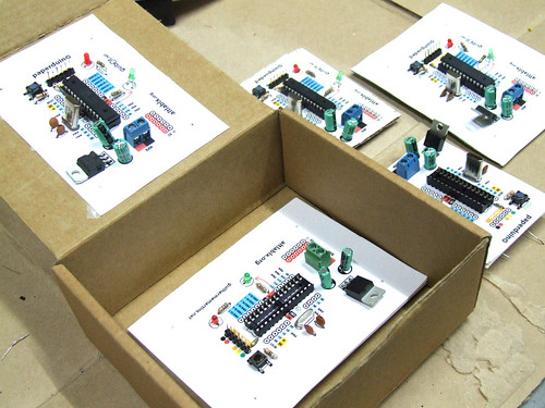
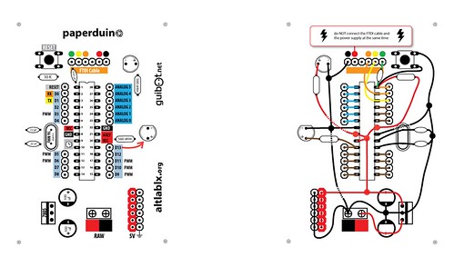
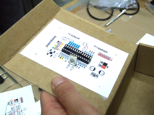
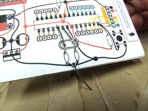
This is a fully functional version of the Arduino. We eliminated the PCB and use paper and cardboard as support and the result is.. the PAPERduino :D
This is the the first version of the layout design, next we will try more designs, and another materials. You just need to print the top and the bottom layout, and glue them to any kind of support you want. We hope that you start making your own boards. If you do, please share your photos with us, we would love to see them ;)
There is no USB direct connection, so to program the paperduino you will need some kind of FTDI cable or adapter. One of this products will be fine: FTDI cable from Adafruit Industries FTDI adapter from Sparkfun
Components list:
1 x 7805 Voltage regulator
2 x LEDs (different colors)
2 x 560 Ohm resistors (between 220oHm and 1K)
1 x 10k Ohm resistor
2 x 100 uF capacitors
1x 16 MHz clock crystal
2 x 22 pF capacitors
1 x 0.01 uF capacitor
1 x button
1 x Atmel ATMega168
1 x socket 28 pin
Female and Male headers
Instructions:
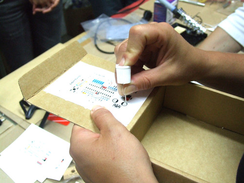
Use a needle to puncture the holes for your components.
Don’t rush, place one component after another and do all the solder work carefully.
Follow the connection lines.
And this should be the final look of your paperduino connections.