Another great Pecha Kucha event, this time I will present GUIBOT’s Motoruino and Farrusco.
See you at Museu da Electricidade this Friday 3rd June??

Author: guibot
Pedro e Inês
Artica was invited by the very popular theater company Teatro O Bando, to create visual scenes to the performance “Pedro e Inês”.

It’s a play about a forbidden love during the Portuguese monarchy in the 14th century, and to better portray certain scenes during the perfomance we were asked to create peculiar visual stuff: fire, deers, rain and other realms to transport the viewer to the peace..it was a “wow” experience! What else could I ask for!?

One of the big challenge’s was the screen, wich wasn’t the conventional white screen, it was a translucent screen, a grid, and due to its reflective nature it turns out to be spectacular for our projections.

Once again we used our “Einstein Video Player” (the same we used in Paint Me) with a couple of enhancements and optimizations:
Performance;
Keystone and VideoPlane manipulation;
Control the application via TouchOSC.
We will talk more about this very soon for sure!!

“Pedro e Inês” is traveling around Portugal, you can check the dates here.
And finally here’s a quick sneak peek to behind the scenes:
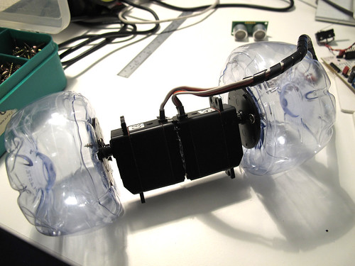
F4WD + ball link
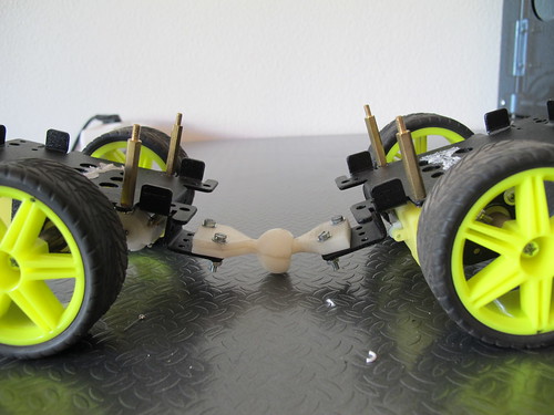
Four wheel drive vehicles have always excited my imagination, and this time I joined two Farrusco’s chassis in front to front as you can see in the picture below:

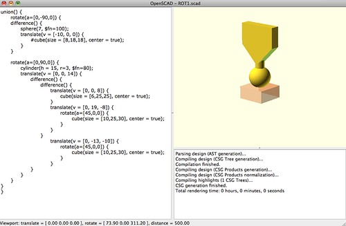
This way both chassis are fixed on each other (is this correct to say in english??) and I thought it would be cool to have them articulated in some way, so I started to design a ball link and this is the first output (oh, did I mention I have a 3D printer in the office? :D
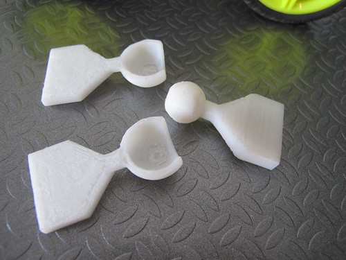
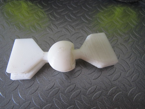
It still need a bit of work because the link needs some kind of lock to prevent the vehicle to bend itself and touch the ground (gosh!! what a crappy english!!)

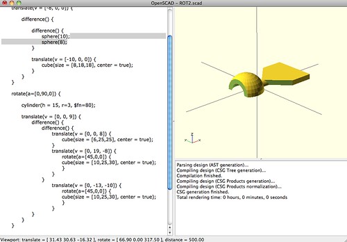
I used OpenSCAD to design the piece, it is a great tool to use because everything is made with simple commands and you can design pretty much everything!! You can download the OpenSCAD files in Thingiverse.
In the next chapter, the redesign!
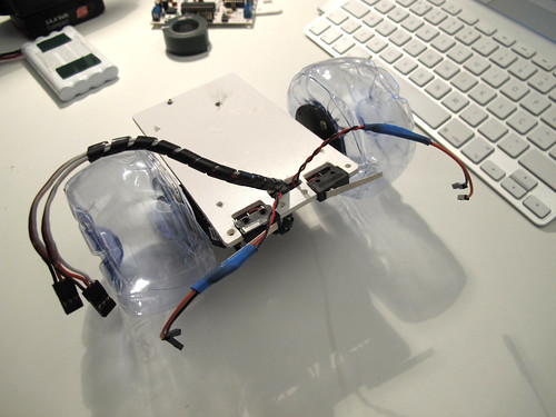
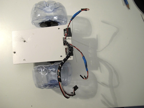
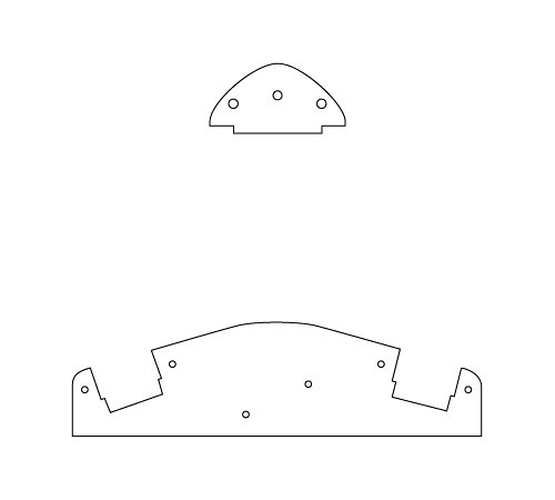
Complexifying BOTtle
I didn’t feel so happy with this minimalistic chassis design so I felt the need to add some complexity to it. And because I am a 3D lover and because I have some spare time I decided to do what I never use to do: “think before act”. Oh, and the other thing that makes me want to do this is the fact that we have a CNC machine at Artica’s office. So althouth I love to build robots without thinking to much on how is it going to be, when there is a cutting machine evolved there is always the need of planning and design wich is a lot of fun as well!
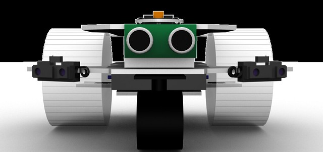
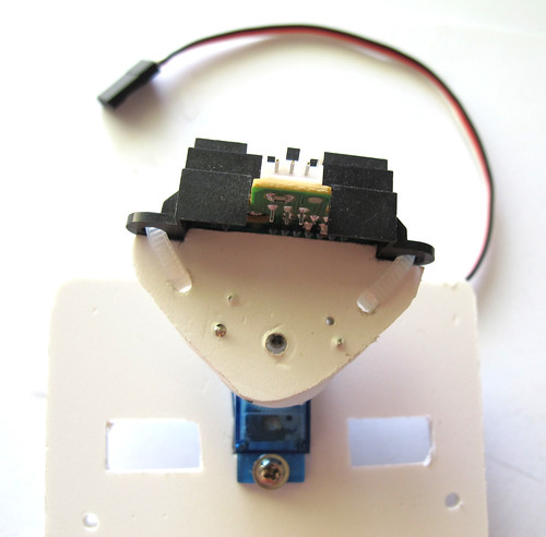
This creature will be able to go in both directions, and for each direction it will have a diferent sensorial setup. On one front there will be an infra-red distance sensor mounted on a servo and two touch sensors to detect colisions. On the other front there will be a sonar distance sensor between two low-range infra-red sensors. This setup will need to use different programming methods for movement and for sensorial perception and will be fun to program.
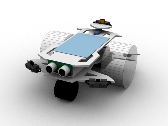
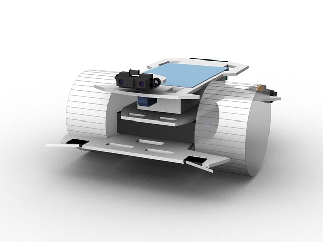
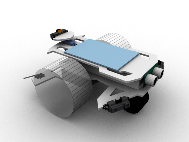
The design is ready, now let the machine do its job.
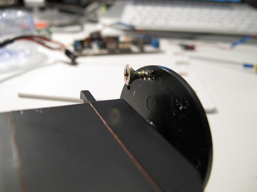
BOTtle
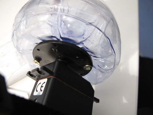
BOTtle is a robot like many others but with a particularity, the wheels are made of plastic bottles as you can see in this video:
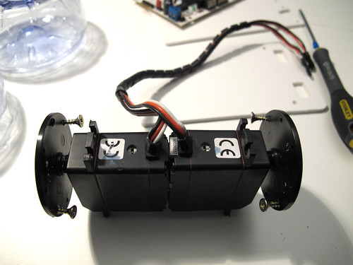
The components I will be using:

The servos are already attached to one another with double side-tape, I will show you how to attach the wheels to the servo horns

Start by adding wood self-tapping screws to the servo horn just a little in a way they won’t fall
Repeat this process 4 times
Open small holes in the exact place where the screws will be tight. I used a soldering iron.
Tight both screws to the wheels
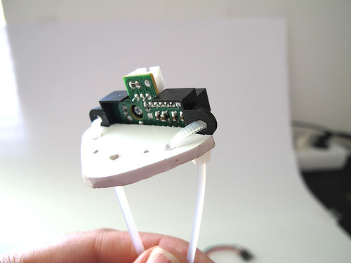
Now I am placing the bumpers on the front of the bot on a PVC sheet (in this post you can see what I have done for a Sharp sensor)

And now the caster wheel, those screws tips are going to be cutted out
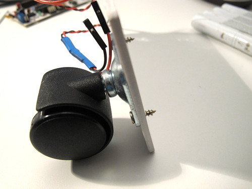
The screw tips are gone and added a bit of super glue because the PVC melted when cutting the screws

To attach the pvc base to the servos I am using double side rubber tape
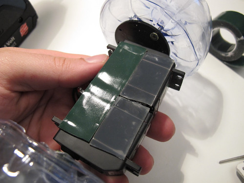
And this is what I have done so far, more will be added soon (I hope)
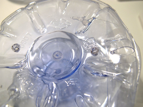
making wheels out of plastic bottles
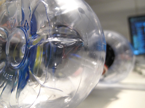
This is an old idea, finally I have the time to show it to the world.
The are bottle shapes that perfectly fit together, you will see how easy it is to create a wheel from two plastic bootles, the video speaks for itself:
Check this post to see how I attached the wheels to a continuos rotation servo.
Clever ways of attaching components to your robot
During the development of Farrusco, we tried a lot of different ways to attach components to PVC supports, from hot-glue, to screws and double side-tape. Because this is intended to be sold as a kit the main keywords were: easy, cheap, last long as possible, and as a final thought “less is more”, what you will see in the fotos below was how André Almeida solved the issue, all credits goes to him. As you see we are using PVC but this can be done with cardboard, wood, acrylic, polymorph, you name it..
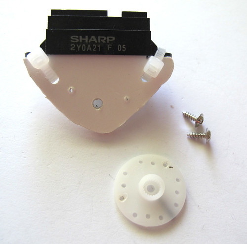
We will show bumper-sensors and a Sharp distance sensor, there won’t be much to say, photos speak for themselves:
What we will use is as simple as this:
Starting with the bumpers, as you see they will fit perfectly inside the holes
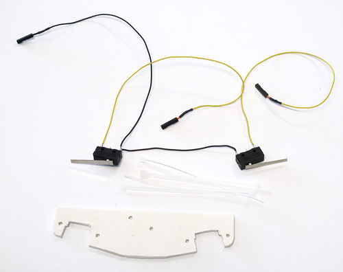
Attach them with zip ties
let’s do the same with the Sharp IR
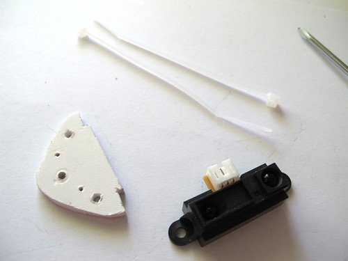
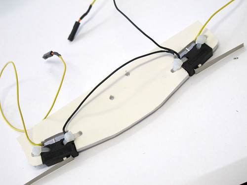
Fits perfectly on the pvc
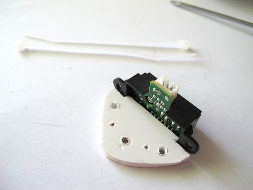
use zipties to attach both to each other
fotos below speak for themselves:
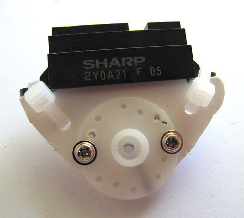
Use your components shape as an advantage and try to be as simple as possible.
Now that you saw this, you can imagine other cool ways to attach other components and sensors to your robots!!
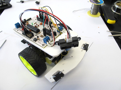
Farrusco, Your First Robot
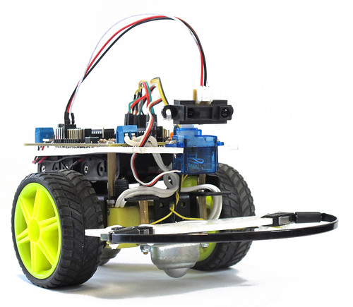
Farrusco is a small robot based on the Arduino platform, in this case, is using a Motoruino wich is inspired on the Arduino but with a couple of enhancements – dc motor dual controller, servo and sensor plugs.
With Farrusco you will be able to make it avoid obstacles, follow walls, enter in free space mode, and in the future more add-ons will be available, just to name a few: line follower, speakers and light sensors, RGB leds, and so on.
This robot is intended to:
– enthusiasts wishing to enter in the creative computing and robotics fields but don’t know where to start;
– engineering and physical computing students who need a development platform;
– digital artists and designers;
– students of all grades;
– be a simple toy.
More information @ guibot.pt/farrusco
This Week In Hobby Robotics 2
Imagine what happen when hobbyists, engeneers, artists and all kinds of cool people from very different backgrounds, gather with a single purpose in common, to create robots, share knowledge and information, and mostly have a lot of fun!
It’s a joy to see my Talkie Walkie being featured in this nice video. Fritsl and Rik, you guys rule!!
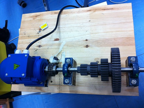
Max + Arduino + Industrial Motor
At Artica, we had a request to link MAXMSP to an industrial motor for an artistic installation witch we will speak about at another time.
This motor is a true beast, and since we have never worked with such a thing we decided to ask for help to our electronics guru David Palma.

The motor controller:
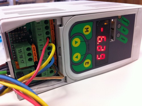
David developed an electronic circuit to simulate a PWM analog output from 0 to 10v (originally it gives 0 to 5v), and another circuit to switch motors direction, both circuits were assembled on a shield and connected to the motor controller.
The first circuit is a transducer:
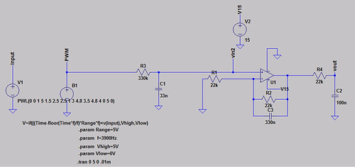
And this is the switch circuit that tell to the motor controller wich direction the motor will spin:
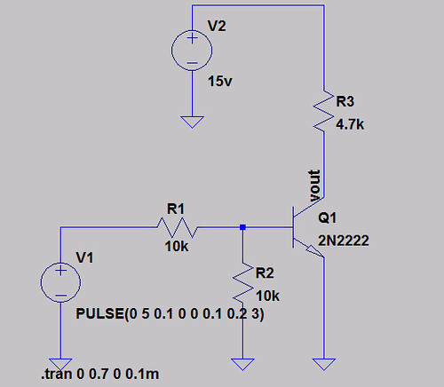
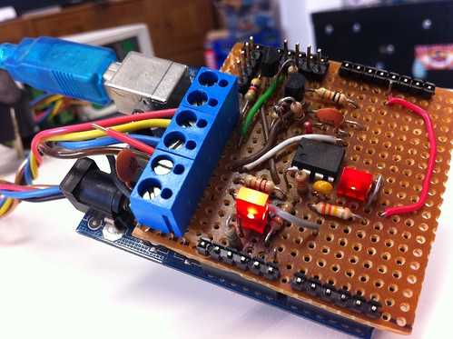
Then he builded an Arduino shield:
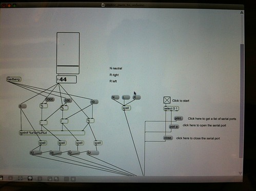
And the final part was the Max patch that send the direction states and the PWM values to the Arduino:
And this is the result:
MAXMSP – ARDUINO – INDUSTRIAL MOTOR from artica on Vimeo.
And last but not the least all the source codes can be downloaded here