The greatest part of the project is to actually drive the bot and just play with it.. video speaks for itself :]
Tag: motoruino
NightRider – update e
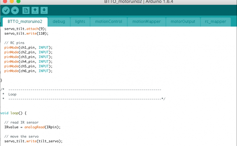
The programming.
To capture the RC data I am using a simple Arduino function called pulseIn(). You can see all the reference on the Arduino site. I discovered this function while googling “radio control joystick to arduino” and found this great example from Sparkfun.
All the code is at github.
There is a folder called “RC_reader” with a program that captures all the 6 RC channels and prints RAW values to the console. This code it is just for debug purposes and it is not being used for anything else:
int ch1_pin = 6; // right_horizontal
int ch3_pin = 5; // right_vertical

int ch2_pin = 4; // left_vertical
int ch4_pin = 3; // left_horizontal

int ch5_pin = 7; // c_stick
int ch6_pin = 8; // right_knob

int ch1_val;
int ch2_val;
int ch3_val;
int ch4_val;
int ch5_val;
int ch6_val;

void setup() {
  Serial.begin(9600);

  // RC pins
  pinMode(ch1_pin, INPUT);
  pinMode(ch2_pin, INPUT);
  pinMode(ch3_pin, INPUT);
  pinMode(ch4_pin, INPUT);
  pinMode(ch5_pin, INPUT);
  pinMode(ch6_pin, INPUT);

}

void loop() {

  ch1_val = pulseIn(ch1_pin, HIGH, 25000); // Read the pulse width of
  ch2_val = pulseIn(ch2_pin, HIGH, 25000); // each channel
  ch3_val = pulseIn(ch3_pin, HIGH, 25000); // Read the pulse width of
  ch4_val = pulseIn(ch4_pin, HIGH, 25000);
  ch5_val = pulseIn(ch5_pin, HIGH, 25000); // Read the pulse width of
  ch6_val = pulseIn(ch6_pin, HIGH, 25000);

  Serial.print("ch1: ");
  Serial.print(ch1_val);
  Serial.print("  ch2: ");
  Serial.print(ch2_val);
  Serial.print("  ch3: ");
  Serial.print(ch3_val);
  Serial.print("  ch4: ");
  Serial.print(ch4_val);
  Serial.print("  ch5: ");
  Serial.print(ch5_val);
  Serial.print("  ch6: ");
  Serial.println(ch6_val);
}
Using this code, I am reading raw data from the RC, now we just need to map this data to an usable format (0 – 1023) or (0 – 255) or (0 – 180).
//The actual code have three important functions:

// map RC RAW values to usable values
rc_mapper();

// map usable values to PWM values
motionMapper();

// controls motion with IR sensor and RC control
motionControl();
rc_mapper() – maps the joystick to a differential drive, and once again google made my day, otherwise I would still be struggling with this component. This function will give two values ‘left_vertical’ and ‘right_horizontal’ that will be used later to assign speed to the motors.
motionMapper() – all the source for this function can be seen here. I had to hack this bit of code to use with the Motoruino2, because the motors are on a Slave uC, I am using a function to set PWM for both motors.
motionControl() – just uses the values that comes from the motionMapper() and sends them through the function setPWM(leftMotor, rightMotor).
I am also using the right knob on the remote controller to set maximum velocity.
There is also a Sharp Distance Sensor that is being used to avoid collisions. On the motion control I am testing the distance, and if it is below 100 the bot runs normally, if it is beyond 100 and below 200 it moves slowly, and if it is beyond 200 stops. It can always move backward, there is still some tweak I want to do here, for instance, I want to be able to enable or disable this feature in runtime.
For the light I am using one of the sticks with 3 positions. Each position gives a value, each value will correspond to a light state.
Not to much to say about the servo control. I just need to verify the course limits to avoid collisions with other components on the bot.

NightRider – update c
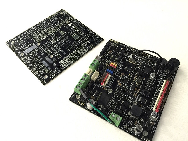
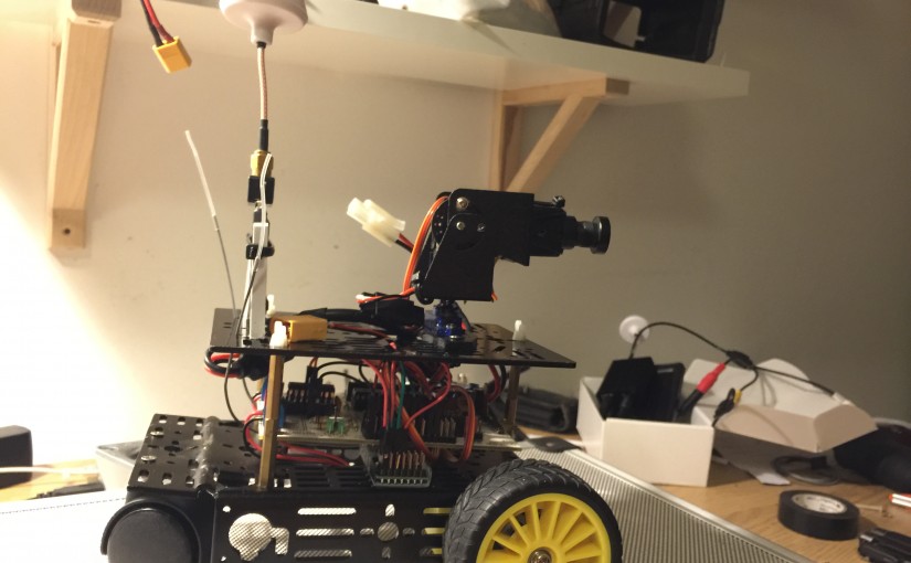
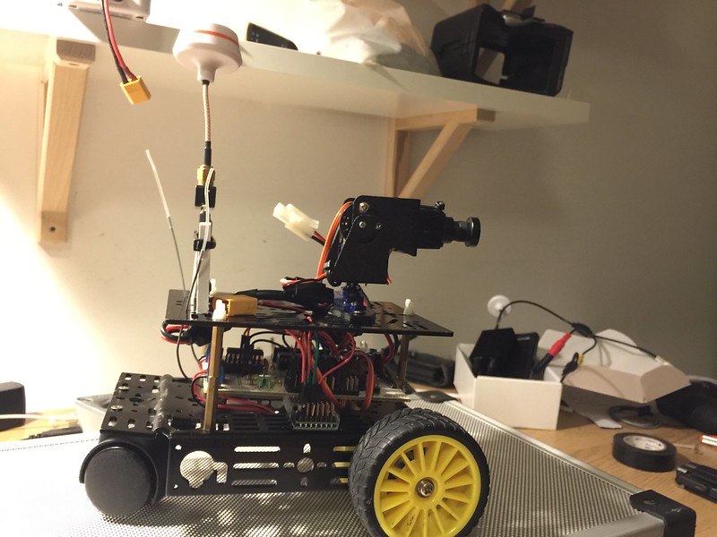
Motoruino2 is a great board, has a built-in IMU, motor encoder connections and an L298 for more power demanding motors, there is a dedicated low-level Arduino (uno) to handle all the raw data from this sensores and actuators. Then, there is a high-level Arduino (Leonardo) that is totally available to whatever we want to do. Both microcontrollers communicate via I2C. There is also a speaker and a microphone that I intend to use later on this project. Also an xbee socket, 1S lipo charger and a mosfet output capable of driving about 2 amps.
Enough said, its a great board and I hope Artica manage a way to put it into the market. Just see for yourself :)
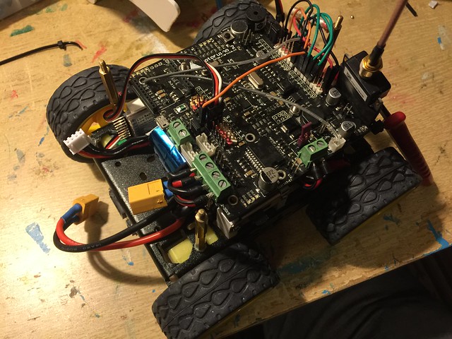
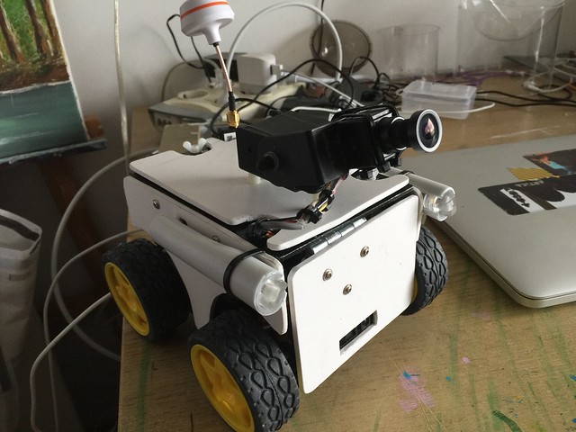
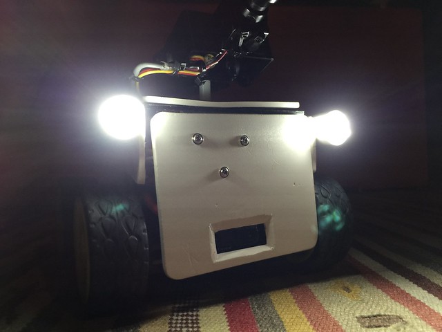
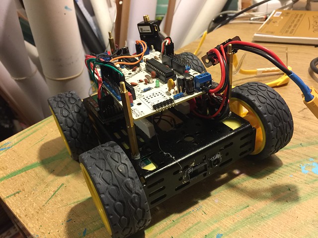
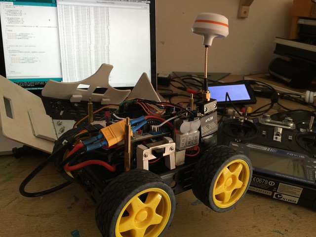
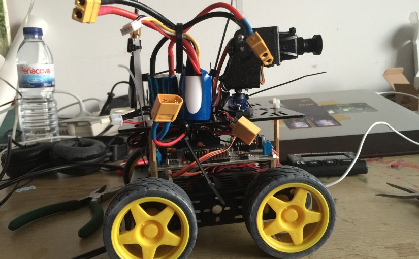
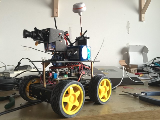
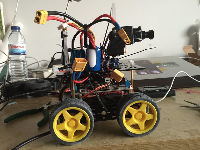
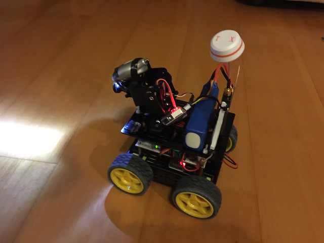
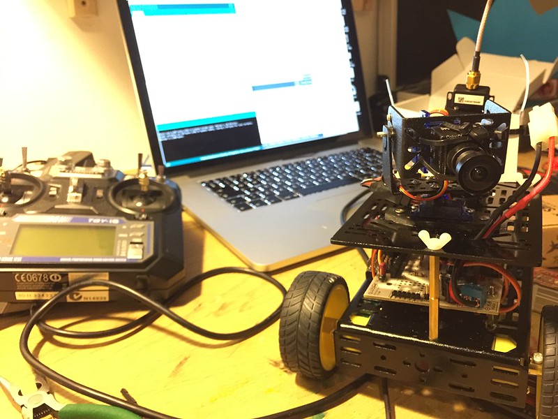
This is how the bot is looking..
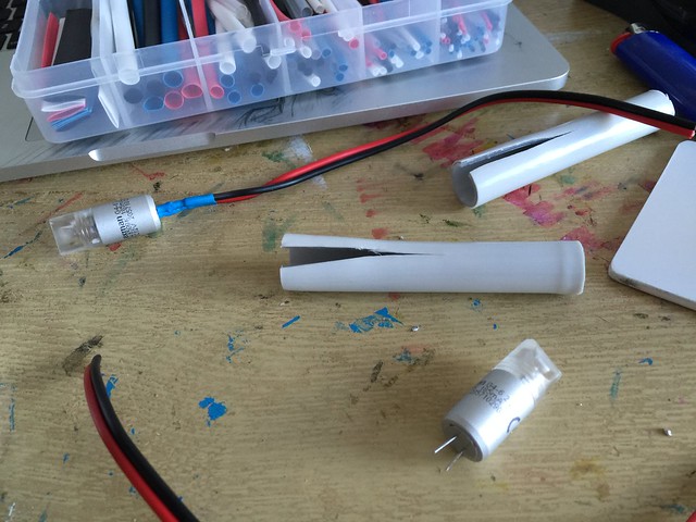
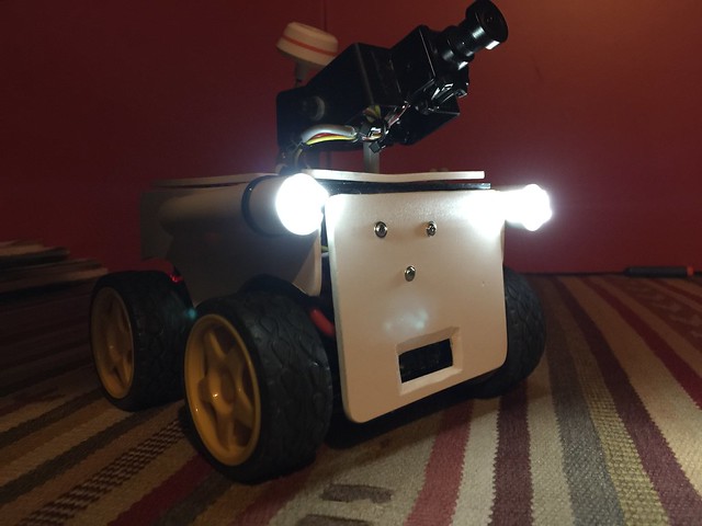
I want to have some lights and I found this little 12v LED lights on the hardware store, this little things in full power completely blind you! To drive the LEDs I am using the mosfet output on the board.
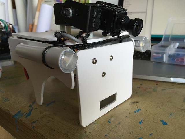
And the shell of course, I changed the pan and tilt system, this is a much robust solution and I removed the pan, if I want to pan I just move the bot side to side.
Et voilá… :D

NightRider – update d
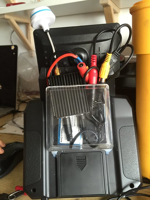
About the controller, I want it to have something we see in the drone industry, a controller with the screen, all-in-one. There is always the option to connect the receiver to the TV, but I really want it to be standalone, independent of power wallets, just something that I can carry anywhere I go.
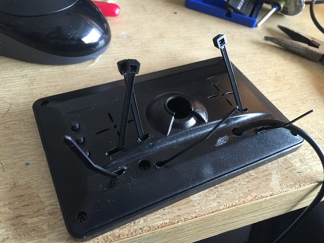
First step was to find a way to hold the screen to the remote, so I added zip ties to the back of the screen.
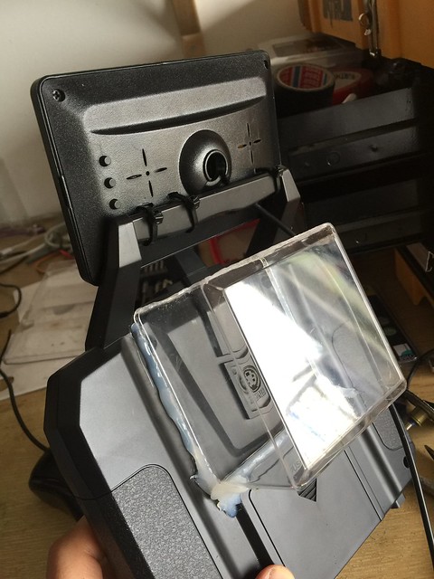
I also added a compartment to hold the receiver, battery and wires (collecting acrylic stuff is a good habit I guess)
Not bad..
The back side is still messy, but I will live with it for now.
and it just works..

NightRider – update b
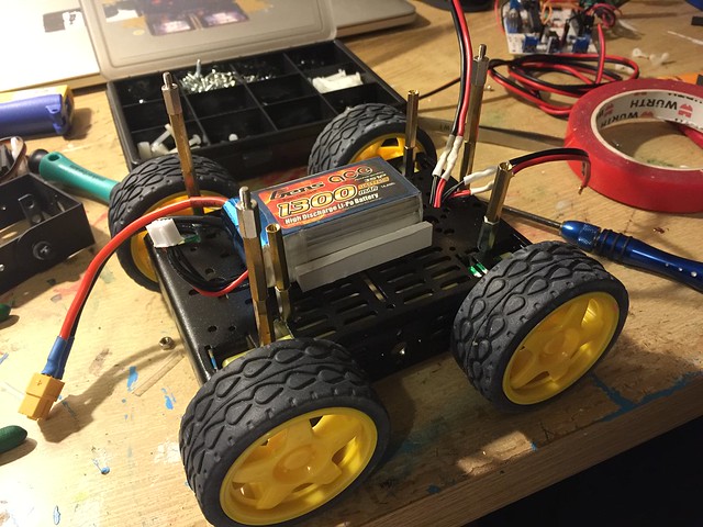
I felt with courage to start the modifications to the bot, first I moved the battery to the lowest possible place, this makes the center of gravity lower.
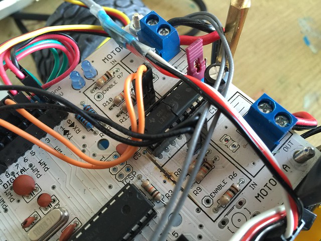
With the electronics board all looks good..
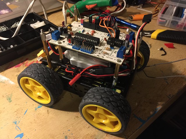
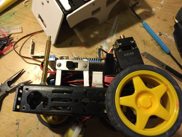
I added a power switch and a Sharp Infra Red sensor, this sensor will act as a fail safe to avoid collisions.
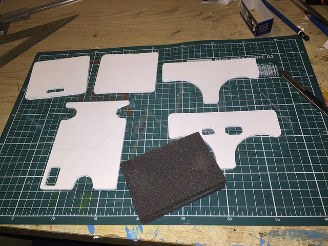
I also wanted to create some kind of a shell, so went to 3D to design the plates and this is the result.
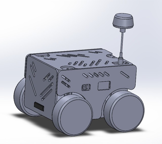
The plates will be cutted in laser or CNC, but meanwhile I will just print them and manually cut PVC sheets.
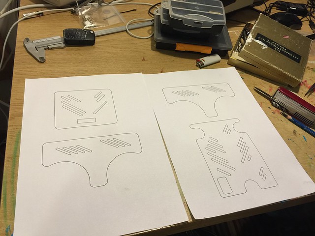
using graphite pencil to transfer the plate drawings to the PVC sheets.
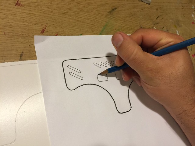
All the plates are transfered and ready to be cutted.

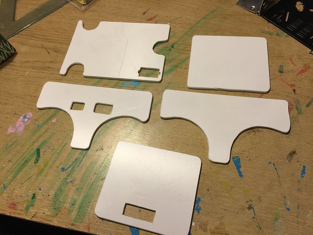
The plates are cutted, now I will just sand a bit to give a final touch
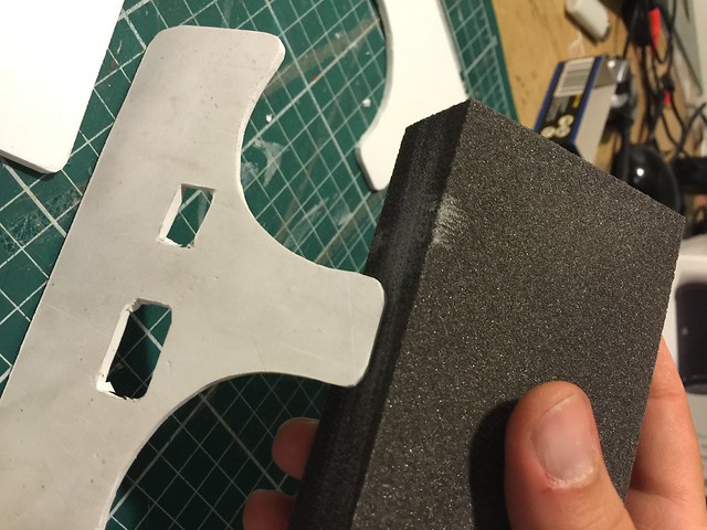
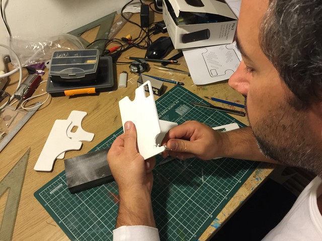
All plates are looking good for now
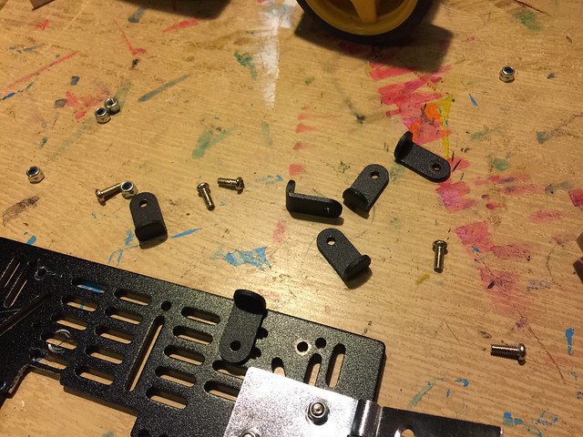
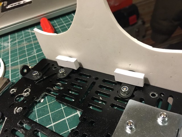
Time to start with the supports for the plates, I will go to these small L shape things
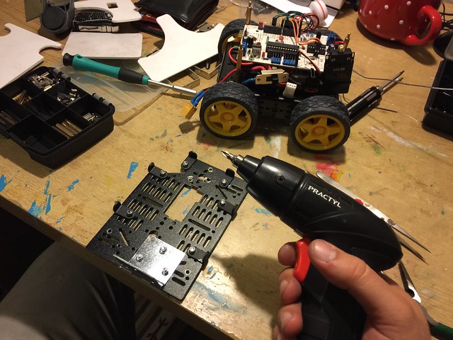
All the supports are fitted, when we have loads of screws an electric screwdriver is handy, this one is the cheapest I could find
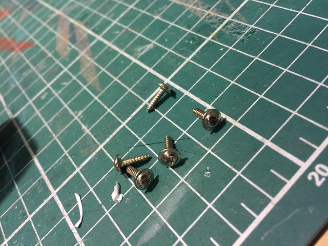
Now to fit the plates I will use this selftap screws, they come together with the servos motors, and I always harvest them because they are hard to find in hardware stores.
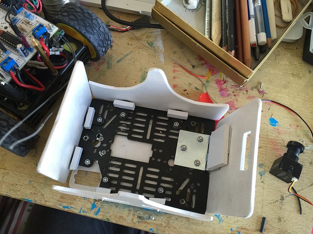
You can also see a hinge, this will actually make a door to swap batteries.
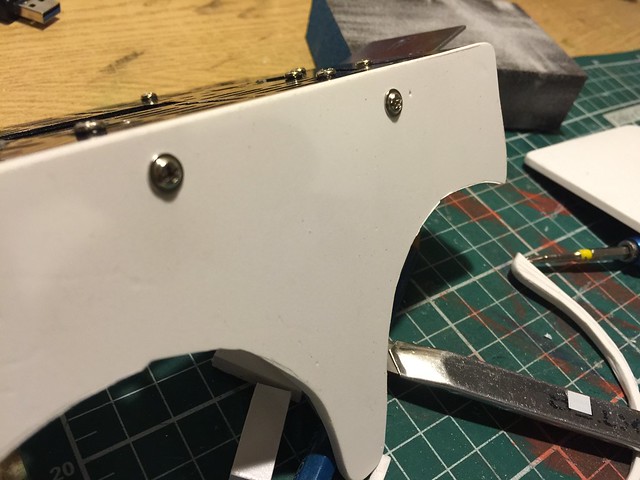
And this is how the plates are securelly fitted.
A look on the inside
This is how I managed to hold the power button in place, it is just PVC pieces fitted to the chassis, and then hold the power button with selftap screws.
There’s the hinge.
Testing everything, all look good.
I was doing another quick test when suddently smoke started to come out, it was the L293D that got smoked.. well, I couldn’t expect worse since I was pushing 12V to 4 motors and the L293D only handles 600 mAh per channel.
I will swap the board to the new Motoruino2 from Artica, wich is still a prototype but nothing better that this bot to test it.
NightRider update A
I wasn’t happy with the hacked chassis, besides the caster wheel was freaking out my wife because it was making a lot of noise on the apartment’s pavement. Luckily me I had another brand new chassis, and so decided to swap all the electronics to the new one, and the result is great, glad I did it! With 4WD it moves really quicly and its motion is much more stable, besides I am feeding the motors with a 12V Lipo battery wich gives it a great pump.
The experiences I had are very fun, and the torch light is a great addon.
I still don’t like the way it is, with the battery exposed on the top GC is very high, besides the pan/tilt is very shaky when it moves in full speed.
I tried my first FPV experience with the Quanum Goggle Set from HobbyKing and it freak me out, running the thing in full speed and all the shakiness made me almost to throw up (lol). The screen that comes with the kit is just great. I think I will buy another kit just to have another screen.
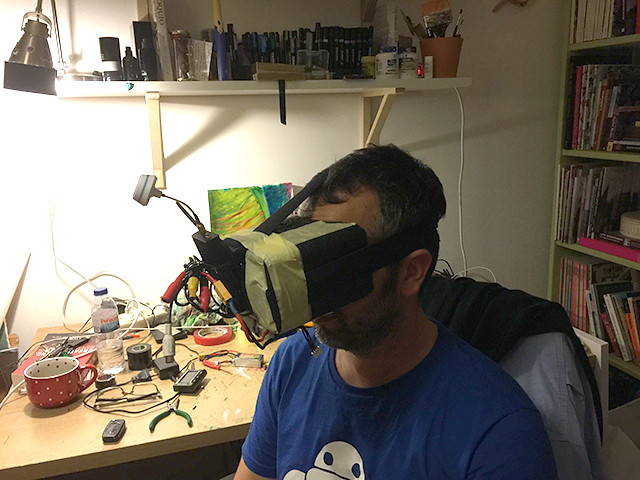
I stick to the screen and connecting the receiver to the TV wich is great.
For now I will try to stick all the electronics inside the chassis and probably will make a shell for it, or at least try.
NightRider
Back to the Origins
Has been a long time since my last robot project.
Recently everything related to FPV, Drones, and Robots in general have been occupying my mind. I wanted to create an FPV Terrestrial Drone experience to anyone without the need of having (in portugal we say “kit the unhas”, “nails kit”) skills to pilot an aerial drone.
This little project reminds me those times when I have time and patience, to build small robotic creatures just because the fun of it, I guess I’m getting very nostalgic with this one.
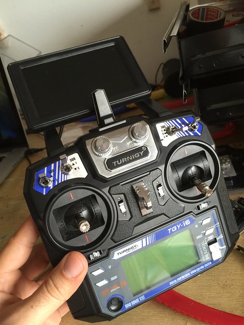
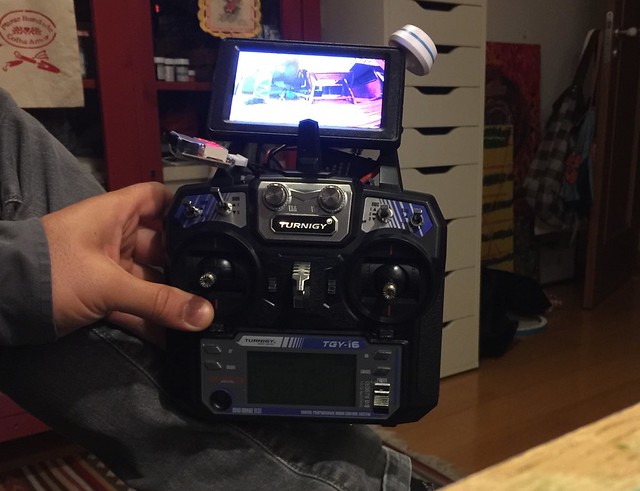
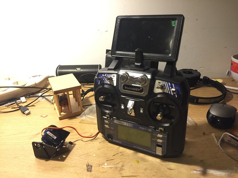
The Turnigy controller works just fine, and to get the sticks values I am using the very well documented code from Sparkfun Nick Poole
https://www.sparkfun.com/tutorials/348
.
And this is the controller with the screen. There is still missing the video receiver and the battery.
More to come ;]
Robotic Claw
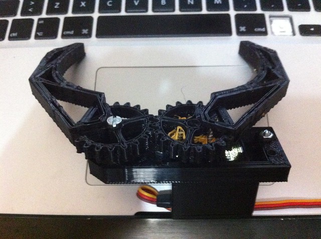
This is a first experiment on building a 3D printed robotic claw, I first got inspired by this project but it was designed for a micro servo, and I wanted to use a standard size servo so I had to design the claw from scratch.
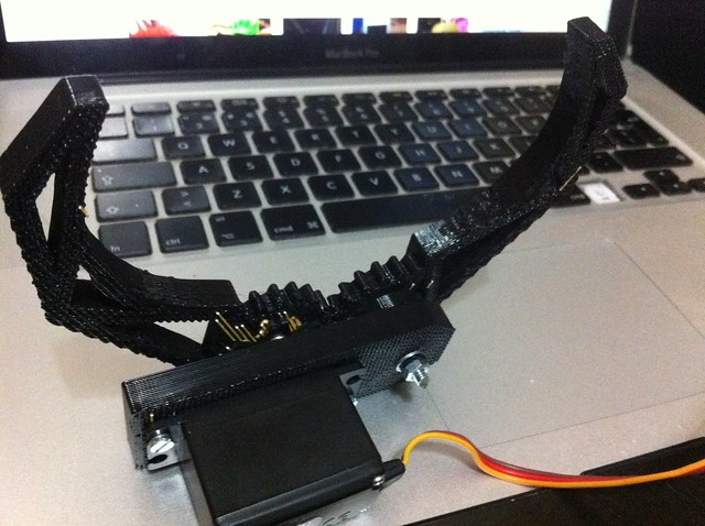
The actual design still need one tweak or two to be optimized for 3D printing, but as it is now is fully functional.
STL files are available at http://www.thingiverse.com/thing:31056
ICU2 – I See You Too
ICU2 is the evolution of the 1st iteration, this new version was totally upgraded, all the pans and tilts systems are from ServoCity, and the software had been re-written from scratch, the face tracker component is on a openFrameworks program wich makes it more performative, and on the Processing side we had a preset based animation program, everytime it looses a face it will load a preset with a diferent animation, this makes it more organic and less repetitive, I will talk more about the software on another post.
This installation is ment to work without the screen, it focuses the attention of the viewer on the ICU, but both of the exhibitions had the screen there as you can see. The knowledge pavilion required the screen to be there because it shows all the control side of the mechanism, and they want to show it to the visitors, and on the FCT Open Day, this exhibition was ment to be visited by new engineering students so we decided to let the screen to be there as well.
Workshop “Introduction to Robotics”
Teatro ABC.PI invited Artica to give a one day “Introduction to Robotics” workshop at “Ponto de Encontro” in Cacilhas (Almada), and the good news is that it is totally free, the not so good news is that you need to hurry up because there is a limitation to 15 participants. This is an initiative of “Quinzena da Juventude” and “Camara de Almada”.