Finally I have some time to continue with this investigation and great improvements were achieved with the circuit provided by Ant: http://www.rev-ed.co.uk/docs/picaxe_sound.pdf
First here are the photos deleted by mistake from flickr:
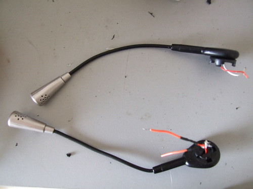
Headsets microphones
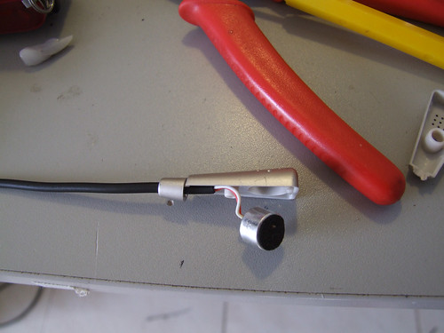
Electrec thingey inside.
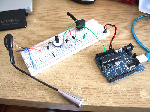
The circuit
This is a closeup of the circuit, I´ve added a 10uF capacitor to stabilize the output signal (it´s the green cap on the right).
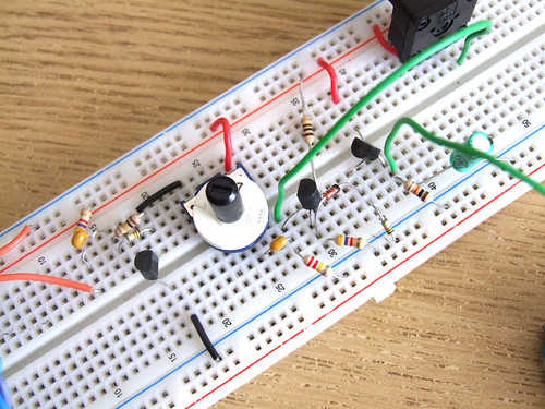
The problem here is that I can´t imagine myself soldering all this components onto a pcb, I would like to have at least two of these, four would be awesome.
Click the following button to see source code for Arduino and Processing
/* ****************************************************
Arduino Code
**************************************************** */
int analogValue;
int val;
void setup()
{
// start serial port at 9600 bps:
Serial.begin(9600);
}
void loop()
{
// read analog input
analogValue = analogRead(0);
// send values to processing
Serial.println(analogValue, DEC);
// pause for 10 milliseconds:
delay(10);
}
/* ****************************************************
Processing Code
**************************************************** */
// import the Processing serial library
import processing.serial.*;
// declare a font variable
PFont font48;
int linefeed = 10; // Linefeed in ASCII
Serial myPort; // The serial port
// value recieved from the serialport / arduino
int sensorValue;
// mapped value
float sensorValueMap;
// – – – – – – – – – – – – – – – – – – – – – – – – – – – – – – – – – – – – – – – – – Setup
void setup() {
myPort = new Serial(this, Serial.list()[0], 9600);
// read bytes into a buffer until you get a linefeed (ASCII 10):
myPort.bufferUntil(linefeed);
size (800, 600);
background (0);
//smooth();
// you need to have this font in your machine, if not go to
// Tools – Creat Font – and create your own font
font48 = loadFont(“alask_48.vlw”);
textFont(font48);
}
// – – – – – – – – – – – – – – – – – – – – – – – – – – – – – – – – – – – – – – – – – Serial Event
void serialEvent(Serial myPort) {
// read the serial buffer:
String myString = myPort.readStringUntil(linefeed);
// if you got any bytes other than the linefeed:
if (myString != null) {
myString = trim(myString);
//println(myString);
// split the string at the commas
// and convert the sections into integers:
int sensors[] = int(split(myString, ‘,’));
// print out the values you got:
for (int sensorNum = 0; sensorNum < sensors.length; sensorNum++) {
//print(“Sensor ” + sensorNum + “: ” + sensors[sensorNum] + “\n”);
// sensor
sensorValue = sensors[0];
//sensorValueSmooth = sensors[1];
}
}
}
// – – – – – – – – – – – – – – – – – – – – – – – – – – – – – – – – – – – – – – – – – Draw
void draw() {
// set the black backgrounf
background(0);
// run the displayText() function
displayText();
// map the recieved values
sensorValueMap = map(sensorValue, 0, 1024, 0, 800);
// draw a rectangle based on the variable sensorValueMap
rect (0, 100, width, sensorValueMap);
}
// – – – – – – – – – – – – – – – – – – – – – – – – – – – – – – – – – – – – – – – – – Display Text
void displayText() {
text(“Sensor Value”, 20, 80);
text(sensorValue, 450, 80);
}
// – – – – – – – – – – – – – – – – – – – – – – – – – – – – – – – – – – – – – – – – – Save image
void keyPressed(){
if(key==’s’)
saveFrame(“sound-######.png”);
}
Hi,
Good work with this project! I’ve been trying to do the exact same thing for a while. I’ve followed the instructions but my mic output is always around 2.5v, and won’t change depending on the amount of sound made. Did you have a similar problem when you tried?
Thanks again,
Lachlan
Something have to be wrong with your circuit because you should be getting readings. Did you double check every connection?
A photo might me useful.
Hi,
I’ve been working on it and have managed to get it working, but the mic doesn’t seem to be sensitive enough. It only changes the voltage if I blow on it, not if I speak or play msuic. It outputs .5v when silent and 3.1v at max. Here’s what I’ve been working on: http://www.filedropper.com/img8468small
Hello. We are doing school project with Arduino board.
We are trying to use the sound sensor too…
We try to find the right components for your circuit.
here is the questions we come across.
can we use this micphone to replace what you have in your set up? (or maybe they are the same?)
http://www.sparkfun.com/commerce/product_info.php?products_id=8669
can we use your piece of code with the microphone i mentioned above?
We are really new to the electronics. I hope that these questions does not bother you…
gloria
Hi! I am not an electronic engineer.. just an enthusiast :) You can ask everything you want.
The microphone I am using is also “Electret”, so I think it is ok.. you just have to figure how to connect it and to read voltage through it.
You are free to use this piece of code! ;) Please send me a link of your project, I will be glad to see it.
hi.
I’ve been making the circuit from the diagram on top of the page, but I’m not getting anything from the serial port (beside zero ;)
Can you post a better photo since I’m probably making some mistakes in te circuit by reading the diagram
good work, nonthess. Amazing sound input.
Hi, sorry I don’t have this circuit on a breadboard anymore, if you send me a good picture I can try to help you.
Good luck
Hi, i wanted to know what the component noted as ‘RV’ for sensitivity control is?
they are potenciometers ;)
Good afternoon
I like your project grade in 1000, could pass some information to capture all that stuff would cancel some frequencies and receives only the frequency approaches.
Thanks
Nice one. But why dont you make a pcb of your own with all the setup? That would be easier to work with I guess….
This was just an experiment, one I surelly will turn this into a pcb ;)
Can you please send me circuit diagram of this project.
hi,
I suppose to build a voice sensor for wheel auto-motion….
eg: if i clap , my vehicle should start/stops and if user say left or right my system moves left n right….will this work using this sound sensor…
hey… cn u plz send the circuit diagram of this project…??? plz…
yes! it will work!
please read the 1st line of the post, thanx :p
Hi!
We’ve built the circuit and all works very well.
There is one question we would like to ask.
In the paper you mention that increasing the capacity of C4 would increase the decay.
What we would like to do is decrease the decay so that we can record sound input at shorter intervals – if possible down to about 300ms. Will decreasing the capacity of C4 do the trick? And if so – what smallest possible capacity would you suggest?
We don’t expect precise values, but it was very nice if you could give us a hint.
Definitly we will show you the project once it’s finished – this should be on Wednesday…
Thanks in advance for any help!
Oliver
this is exactly what i’m looking for ! but as i’m just a beginner of electronic , i would like to “copy ” and “tinking ” the way you make this , but i can’t read the electronic circuit plan. so could you please if possible send me a good definition photo of this one : http://farm4.static.flickr.com/3656/3496460969_d6f3e8e836.jpg?v=0
thanks so much !!
I want to know is it possible to use this sound sensing circuit to Microchip Micro-controller?
if your micro controller has an analog
Input you can definetly use this circuit ;)